
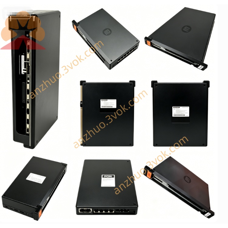
0-57C401
Description
Model Definition
0-57C401: Full part number (the leading "0" denotes a factory-original, unmodified unit)
57C401: Core model number (used for cross-referencing and ordering)
-2: Common suffix (indicates revision 2, the most prevalent hardware version)
Series: AutoMax 57C Series (Reliance’s flagship PLC I/O line)
Technical Specifications
General
Brand: RELIANCE (Reliance Electric / Baldor Reliance)
Type: Digital Drive I/O Module
Weight: 0.91 kg (2.0 lbs)
Dimensions: Standard AutoMax rack-mount form factor (1 slot width)
Operating Temperature: 0°C to +55°C
Storage Temperature: -40°C to +70°C
Humidity: 5%–95% non-condensing
Certifications: CE, RoHS compliant
I/O Characteristics
Total Channels: 20 (labeled A1–I2 on the front panel)
Input Voltage: 10–30 VDC (digital)
Output Voltage: 0–10 VDC (digital drive control)
Signal Frequency: Up to 10 kHz
Accuracy: ±0.1% (signal conditioning)
Isolation: Opto-isolated channels (250 Vrms isolation voltage)
Electrical
Power Supply: 5 VDC (from AutoMax backplane)
Current Draw: 0.8 A (typical)
Fuse Protection: Onboard replaceable fuse (1 A)
Interface & Communication Configuration
Physical Interfaces
Front Panel: 20 rectangular I/O ports (A1–I2) for field wiring
Backplane: AutoMax proprietary edge connector (for rack communication and power)
LED Indicators:
M STATUS: Module health status
RUN: Active operation indicator
RUN PERM: Run permission status
DFR/FMCR/RMCR/MCR: Drive fault and control status LEDs
Communication
Bus Protocol: AutoMax Backplane Bus (proprietary, high-speed parallel communication)
Data Rate: 2 Mbps (backplane)
Compatibility: AutoMax PLC racks (57C series chassis)
Core Functions
Digital Signal Processing: Converts between controller logic signals and drive-compatible digital I/O.
High-Density I/O Expansion: Provides 20 channels for connecting drives, sensors, and actuators.
Real-Time Drive Control: Enables precise on/off control of industrial drives (e.g., motors, valves).
Fault Monitoring & Reporting: Monitors drive status via dedicated LEDs and backplane communication.
Electrical Isolation: Protects the controller from field-side voltage spikes and noise.
Application Scenarios
Legacy AutoMax System Retrofits: Replacement for failed 57C401 modules in existing installations.
Motion Control Systems: Interface between AutoMax PLC and servo/vector drives in manufacturing lines.
Process Control: Signal conditioning for digital sensors (limit switches, proximity sensors) in steel, pulp & paper, and power industries.
Material Handling: Control of conveyors, cranes, and automated guided vehicles (AGVs).
Usage & Maintenance Instructions
Installation
Ensure the AutoMax rack is powered off before installation.
Align the module with the rack slot and insert firmly until the backplane connector seats.
Secure the module with the rack’s captive screws.
Wire field devices to the front-panel ports (A1–I2) per the system schematic.
Operation
Power-On: The PWR LED illuminates; RUN flashes during initialization (≈5 seconds).
Normal Operation: RUN LED is steady; M STATUS is green (healthy).
Fault Conditions:
M STATUS (Red): Module hardware fault (check fuse or replace module).
DFR (Red): Drive fault (inspect connected drive wiring).
Maintenance
Preventive Inspection: Quarterly check of wiring tightness and LED status.
Fuse Replacement: If the PWR LED is off, power off the rack and replace the 1 A onboard fuse.
Cleaning: Use compressed air (low pressure) to remove dust from the front panel and connectors.
Get a Quote