
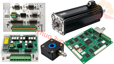
Bosch Rexroth DDC01.1-K100A-DL01-01-FW Inquiry Product
Description
1. Part Number Breakdown
DDC: Digital Drive Controller (compact servo drive)
01.1: Series 01, hardware revision 1
K100A: K=compact; 100=100 A; A=analog base
DL01-01: D=digital feedback; L=DLC positioning + analog; 01=func code; 01=variant
-FW: Firmware suffix – indicates drive is supplied with or requires dedicated firmware (not blank/hardware-only)
2. Technical Specifications (Electrical / Mechanical)
Electrical
Input: 3×AC 380–460 V, 50/60 Hz
Control Voltage: 24 VDC
Continuous Output: 100 A
Peak Output: 200 A (1 s)
DC Bus: Integrated rectifier, ~700 VDC
PWM Frequency: 4 kHz
Mechanical & Environmental
Dimensions (H×W×D): 360 × 155 × 261 mm
Weight: ~12.5 kg
Protection: IP65 (machine-mountable)
Operating Temp: 0 °C to +45 °C (full load)
Storage Temp: −20 °C to +80 °C
Control & Interfaces
Modes: Position (DLC) / velocity / torque
Feedback: Digital servo (MDD motor, multiturn encoder)
Command: DLC 2.1 positioning bus + ±10 V analog
Comm: RS-232/RS-485 (diagnostics), DLC bus
Protection: Overcurrent, overvoltage, overtemperature, short circuit, STO
3. What “FW” Means (Critical Difference)
No suffix (e.g., DL01-01): Hardware-only, firmware must be loaded separately (not included)
-FW suffix (DL01-01-FW): Firmware is part of the part number – supplied with standard DL01-01 firmware, or ordered as a firmware-bearing unit
Why it matters: For spare parts/retrofits, -FW = ready to run (no separate firmware file needed)
4. DL01-01-FW vs Other DDC Interfaces
DA: Only analog ±10 V
DG: Analog + RS-485 digital
DS: Only digital (SERCOS)
DL-FW: DLC positioning + analog, firmware included
Best for: Single-axis positioning, CNC retrofits, mixed analog/DLC systems
5. Applications
CNC machine tools (milling, turning, grinding)
Single-axis positioning systems
Retrofit projects (analog → DLC positioning)
Industrial automation with mixed control types
Get a Quote