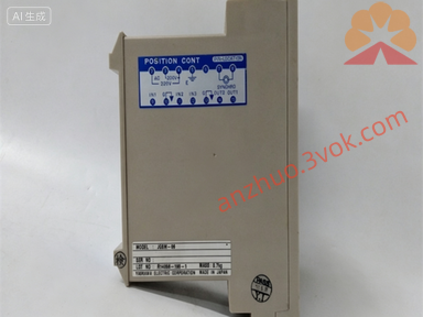
CACR-SR15SB1AF-Y100
Description
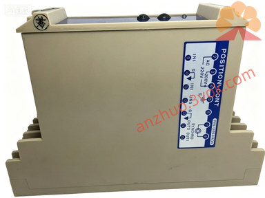
I. Safety Instructions (Must Read) • High Voltage Hazard: Within 5 minutes after power is turned on and off, there is still high voltage at the terminals. Do not touch. • Reliable Grounding: The driver and the motor must be grounded at a single point, with the grounding resistance ≤ 10Ω. • Prohibition of Modification: -Y100 is a custom firmware from the original manufacturer. It cannot be flashed with ordinary SR15 programs; otherwise, there will be alarms / non-operation. • Environmental Requirements: 0–40℃, humidity ≤ 80% RH (no condensation), no dust / corrosive gases. II. Panel and Terminal Instructions • Panel Buttons: ◦ MODE: Switch between monitoring / parameter / fault modes ◦ SET: Confirm / enter parameters ◦ ↑/↓: Increase / decrease values ◦ RUN/STOP: Local operation / stop • Main Circuit Terminals: ◦ R/S/T: Three-phase AC200–230V input ◦ U/V/W: Connect servo motor ◦ P/B1: Connect regenerative braking resistor (optional) ◦ G: Ground • Control Signal Terminals (CN1): ◦ SG: Signal Ground ◦ IN1–IN4: Position pulse / direction input ◦ OUT1–OUT2: Alarm / positioning completion output ◦ +5V: Encoder power supply III. Installation and Wiring Steps 1. Installation: Install vertically in the control cabinet, leaving ≥ 50mm of space on both sides for heat dissipation, and no obstruction at the bottom fan opening. 2. Wiring Sequence: ◦ Connect the motor U/V/W and encoder wires (CN2) first ◦ Then connect the control signal CN1 ◦ Finally, connect the main circuit R/S/T and ground wire 3. Wiring Specifications: Power wires ≥ 2.5mm², signal wires use shielded twisted pair, with the shielding layer grounded at one end.
IV. Parameter Settings (Basic) • Enter parameter mode: Press MODE → Input password (default 0000) → SET • Core parameters (customized Y100 is preset, do not modify): ◦ Cn-01: Control mode (0 = position, 1 = speed) ◦ Cn-02: Motor model (match 1.5kW incremental motor) ◦ Cn-03: Pulse equivalent (default 1000p/r) ◦ Cn-04: Electronic gear ratio (Y100 customized fixed) • Save parameters: After modification, press SET → Display "End" to indicate successful saving. V. Operation 1. Local trial run (JOG): ◦ MODE → Select JOG → SET → Move the motor by pressing ↑/↓ ◦ Speed defaults to 500rpm, which can be adjusted in Cn-05 2. Remote control (default): ◦ External PLC sends pulses + direction signal to CN1 ◦ The driver automatically executes positioning, OUT2 outputs "Positioning completed" 3. Stop mode: ◦ Normal stop: Send stop signal or use STOP key ◦ Emergency stop: Cut off main power or external emergency stop switch VI. Fault Codes and Handling • A.10: Overcurrent → Motor short circuit / Wiring error / Overloaded load • A.31: Overvoltage → Power supply voltage too high / Brake resistor open circuit • A.40: Overheating → Fan blockage / Poor heat dissipation / Environmental temperature exceeds 40℃ • A.80: Encoder fault → Encoder wire broken / Poor contact / Encoder damaged • Handling process: Power off for 5 minutes → Check wiring / Load → Restart → If still alarming, contact the manufacturer. VII. Daily Maintenance • Daily: Check fan operation, no alarms on the panel • Weekly: Clean the fan filter dust • Monthly: Tighten terminal screws, check cable aging • Long-term shutdown: Power off and cover with a dust cover to avoid moisture. VIII. Replacement and Compatibility • Unique replacement part: Must be CACR‑SR15SB1AF‑Y100 • Prohibited substitution: Ordinary CACR‑SR15SB1AF or other shells (BY/BZ/BE) models • Customization note: -Y100 includes dedicated I/O logic, gain parameters, motion sequence, and cannot be used universally.

Get a Quote