
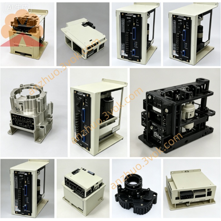
JANCD-MEW02
Description
II. Technical Specifications
Brand: YASKAWA (Yaskawa)
Model: JANCD-MEW02 (MEW02-1/-2)
Compatible control cabinets: XRC, MRC series robots
Power supply: DC 24V ±10%
Input: 32 points of optically isolated (NPN/PNP compatible)
Output: 32 points of transistors / relays (optional)
Internal bus: High-speed communication with XRC mainboard
Operating temperature: 0℃~55℃
Storage temperature: -20℃~80℃
Humidity: ≤95% RH (no condensation)
Power consumption: ≤30W
Weight: Approximately 0.4kg
III. Installation and Wiring Installation
The standard slots of the XRC/MRC control cabinet must be unplugged and reinserted while the power is off.
Align the guide rail and push in, then lock the fixing screws to ensure that the backplane gold fingers are in good contact.
Wiring
Power: DC24V connects to terminal CN1 (corresponding to the positive/negative pole).
Input: Peripheral switch / sensor signal connects to CN2 - CN5.
Output: Contactors, solenoid valves, etc. loads connect to CN6 - CN9.
Grounding: The board card GND is reliably connected to the control cabinet ground to reduce interference.
V. Maintenance and Care
Daily: Observe the RUN (green) / ERR (red) indicator lights to confirm the I/O status and communication is normal.
Regularly (every 3 months): Unplug for dust cleaning; check for loose or oxidized connectors; clean the gold fingers; tighten the terminals.
Long-term: Avoid high temperature, humidity, and strong vibration environments; store spare parts in a dry environment.
VI. Fault Troubleshooting
I/O no response
Check if the DC24V power supply is normal; reinsert the board card; check for external line short circuit / open circuit.
Input abnormal (lamp not lit / constantly lit)
Measure the input terminal voltage; check the photoelectric isolation module; replace the board card for testing.
Output does not act
Check the output type (transistor / relay); check the load wiring and power supply; replace the board card.
Communication error (ERR red flashing)
Clean the backplane gold fingers; check the internal bus connection; troubleshoot the on-site electromagnetic interference.
Get a Quote