
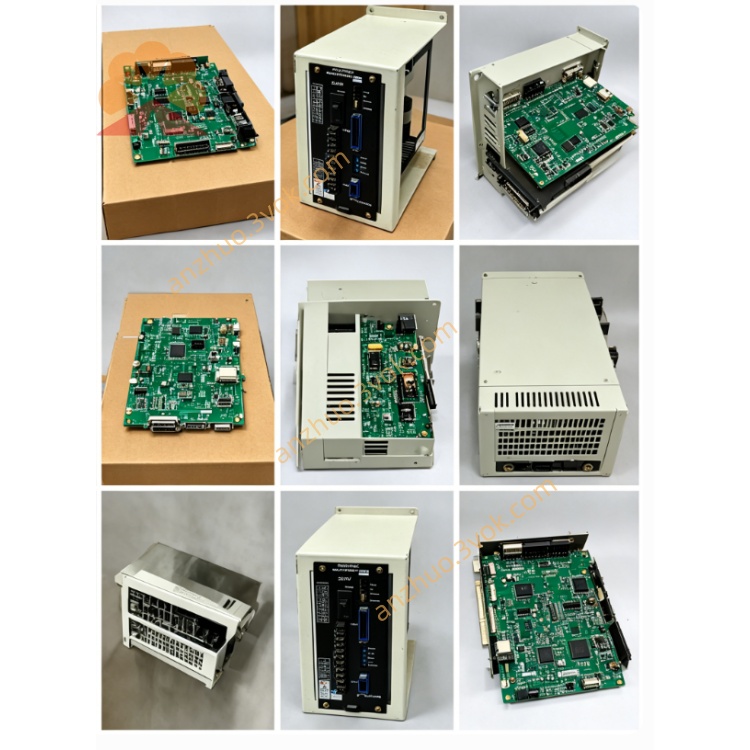
JANCD-MCV01
Description
II. Technical Specifications
Brand: YASKAWA (Yaskawa)
Model: JANCD-MCV01
Compatible Controller: XRC, NX100 series robot control cabinet
Power Supply: DC 24V ±10%
Power Consumption: ≤ 25W
Communication Bus: MECHATROLINK-II (for servo)
Number of Control Axes: Up to 6 axes (robot body) + 3 axes (external axes)
Operating Temperature: 0℃~55℃
Storage Temperature: -20℃~80℃
Humidity: ≤ 90% RH (no condensation)
Certifications: CE, UL
III. Installation and Wiring Installation
The dedicated slot for the control cabinet must be unplugged before insertion.
Align and push it into the guide rail, then tighten the screws to ensure a good contact of the back panel.
Wiring
Power supply: Positive and negative terminals of DC24V correspond to the terminals, and be tightened without loosening.
Communication: Connect the MECHATROLINK-II bus to the servo amplifier, with the shielding layer grounded at one end.
Grounding: Connect the board card ground to the control cabinet ground reliably to reduce interference.
V. Maintenance and Care
Daily: Observe the LED status lights (RUN/COM/ERR) to confirm normal communication.
Regularly (every 3 months): Unplug and blow off dust; check for any looseness or oxidation of the connectors; verify the torque of the wiring terminals.
Long-term: Avoid high temperatures, humidity, and vibrations; store spare parts in a dry environment with sealing.
VI. Fault Diagnosis
Servo communication error (LED flashes red)
Check the MECHATROLINK cables and connectors; verify the terminal resistor settings.
Reinsert the board card; if still abnormal, replace the MCV01 board card.
Power failure (PWR light does not light up)
Measure the DC24V voltage; check for short circuits or loose connections between the power supply module and the wiring.
No response from the axis
Confirm that the board card and the back panel are in good contact; check the power supply and status of the servo amplifier.
Data jitter / packet loss
Check the grounding; investigate on-site electromagnetic interference; replace the shielded cable.
Get a Quote