
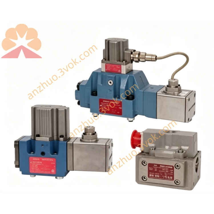
MOOG D633-521B Direct Drive Servo Valve
Description
1.1 Intended Use
This manual applies to the Moog D633-521B direct-drive servovalve (DDV), a high-precision electrohydraulic control unit for industrial hydraulic systems. It is designed for 4-way/3-way directional, velocity, pressure, and force control using mineral oil-based hydraulic fluids (per DIN 51524).
1.2 Safety Symbols
⚠️ Warning: Risk of injury or equipment damage.
⚠️ Caution: Risk of equipment damage.
ℹ️ Note: Important operational information.
1.3 Qualified Personnel
Installation, operation, and maintenance must be performed by trained electrohydraulic technicians familiar with hydraulic safety standards (EN 982, DIN EN 50018/50019).
2. Product Description
2.1 Overview
The D633-521B is a size 03 (NG6) direct-drive servovalve with integrated electronics and a linear force motor (permanent magnet type). It features closed-loop spool position control via an LVDT (Linear Variable Differential Transformer) for high accuracy and dynamic response.
2.2 Type Designation Breakdown (D633-521B)
D633: Series (direct-drive servovalve, size 03)
521: Flow/pressure/configuration code
B: Seal/material/connector variant (standard: HNBR seals, M12 connector).
2.3 Technical Specifications
2.3.1 Hydraulic Data
Mounting Pattern: ISO 4401-03-03-0-94
Rated Flow: 75 L/min (Δp = 5 bar per land, ±10% tolerance)
Max Operating Pressure: P/A/B ports: 350 bar; T port: 50 bar (350 bar with Y port)
Fluid Compatibility: Mineral oil (ISO 4406 cleanliness class 15/12 or better)
Viscosity Range: 5–400 mm²/s (recommended: 15–100 mm²/s).
2.3.2 Electrical Data
Supply Voltage: 24 VDC (19–32 VDC)
Current Consumption: ≤1.2 A (D633K variant)
Command Signals (differential):
Voltage: 0 to ±10 V (input resistance: 10 kΩ)
Current: 0 to ±10 mA (floating) or 4–20 mA
Feedback Signal: 4–20 mA (spool position, 12 mA = centered)
Connector: M12 (5-pin), IP67 rated.
2.3.3 Environmental Data
Ambient Temperature: -20 °C to +60 °C
Fluid Temperature: -20 °C to +70 °C
Vibration Resistance: 30 g (3-axis)
Mass: 2.5 kg.
3. Installation
3.1 Mounting Surface Requirements
Flatness: 0.01 mm per 100 mm
Surface Roughness: Ra < 0.8 µm
Cleanliness: Free of debris, burrs, and old sealant (use lint-free wipes).
3.2 Mounting Procedure
Remove protective covers from valve ports and mounting surface.
Align valve with ISO 4401-03 mounting pattern; ensure O-rings are properly seated.
Use M5×55 socket head cap screws (10.9 grade); tighten diagonally in sequence to 6.8 Nm ±10%.
Verify no port misalignment or O-ring extrusion.
3.3 Electrical Connection
3.3.1 M12 Connector Pinout
表格
| Pin | Function | Description |
|---|---|---|
| 1 | +24 VDC | Power supply positive |
| 2 | 0 VDC (GND) | Power supply negative |
| 3 | Signal GND | Command/feedback reference |
| 4 | Command (D) | Differential command (+) |
| 5 | Command (E) | Differential command (-) / Feedback |
3.3.2 Wiring Guidelines
Use shielded cables (≥0.75 mm² cross-section); shield to be grounded at supply end only.
Avoid running cables parallel to high-voltage power lines (maintain ≥30 cm distance).
Torque M12 connector to 2.5 Nm; ensure IP67 seal is intact.
4. Start-Up
4.1 Pre-Start Checks
Confirm hydraulic system cleanliness (ISO 4406 15/12 or better).
Verify all electrical connections are secure and insulated.
Check valve for physical damage (dents, cracked housing).
Ensure hydraulic fluid level is correct and filters are installed (β₁₀ ≥75, 10 µm absolute).
4.2 System Flushing
Replace D633-521B with a flushing plate or directional valve.
Flush system at operating temperature until cleanliness class 15/12 is achieved.
Reinstall servovalve; replace flushing elements with high-pressure filters.
4.3 Initial Operation
Power on 24 VDC supply; verify no fault codes (LED indicator: green = normal, red = fault).
Apply 0 VDC command signal; spool should center (feedback = 12 mA).
Gradually increase command signal to ±10 VDC; monitor spool movement and hydraulic response.
Check for external leaks at mounting surface, ports, and connector.
Vent hydraulic system to eliminate air (critical for avoiding "diesel effect" damage).
5. Operation
5.1 Normal Operation
Command Signal: 0 to ±10 VDC (or 4–20 mA) controls spool position proportionally.
Feedback Signal: 4–20 mA provides real-time spool position monitoring (12 mA = centered).
Fail-Safe: On power loss or command signal failure, spool returns to spring-centered position (neutral).
5.2 Operating Limits
Do not exceed 350 bar at P/A/B ports.
T port pressure must not exceed 50 bar (350 bar only if Y port is connected to tank).
Avoid temperature fluctuations >10 °C during operation.
Do not operate with contaminated fluid (risk of spool/bushing wear).
6. Maintenance
6.1 Routine Maintenance
Daily: Visual inspection for leaks, damaged cables, or loose connectors.
Monthly: Check filter pressure drop; replace if clogged.
Quarterly: Verify electrical connections and shield integrity.
Annual: Recalibrate spool position feedback (per Moog calibration procedure).
6.2 Cleaning
Use lint-free cloths and non-abrasive cleaners for external surfaces.
Do not use solvents on seals or electrical connectors (risk of damage).
Keep ports covered when not in use to prevent contamination.
6.3 Seal Replacement
Replace O-rings every 2 years or if leaks are detected.
Use only Moog OEM seals (HNBR material, part number: C55856-001).
Follow mounting procedure (Section 3.2) for reassembly.
7. Troubleshooting
7.1 No Hydraulic Response
Possible Causes: No 24 VDC supply; faulty command signal; spool jammed; clogged ports.
Remedies: Check power supply; verify command signal wiring; clean spool/ports; replace filters.
7.2 Unstable Operation (Oscillation)
Possible Causes: System resonance; insufficient damping; contaminated fluid; misaligned spool.
Remedies: Adjust controller gains; check fluid cleanliness; recalibrate spool position; verify mounting surface flatness.
7.3 External Leaks
Possible Causes: Loose mounting bolts; damaged O-rings; cracked housing.
Remedies: Retighten bolts to 6.8 Nm; replace O-rings; contact Moog for housing repair/replacement.
7.4 Electrical Faults (Red LED)
Possible Causes: Overvoltage; short circuit; faulty LVDT; damaged electronics.
Remedies: Check supply voltage; inspect wiring for shorts; contact Moog for electronics repair.
8. Storage & Transportation
8.1 Storage
Store in clean, dry environment (temperature: -20 °C to +60 °C; humidity: <60%).
Keep ports covered with protective caps; store in original packaging if possible.
Do not store for >5 years without inspection (contact Moog for service).
8.2 Transportation
Use shock-absorbent packaging; avoid vibration and impact.
Keep valve in upright position; do not expose to extreme temperatures.
Mark packaging as "Fragile - Precision Instrument".
9. Warranty & Support
9.1 Warranty
This D633-521B servovalve is covered by a 12-month warranty from date of purchase, covering defects in materials and workmanship. Warranty is void if:
Valve is modified or repaired by unauthorized personnel.
Damage results from misuse, contaminated fluid, or improper installation.
Serial number is altered or removed.
9.2 Technical Support
For technical assistance, calibration, or repair, contact Moog Industrial Group:
Website: www.moog.com
Service Email: industrial.service@moog.com
Phone: +1-716-652-2000 (US), +49-89-99616-0 (Europe).
10. Declaration of Conformity
Moog GmbH declares that the D633-521B series servovalves comply with the following directives and standards:
Machinery Directive: 2006/42/EC
EMC Directive: 2014/30/EU
RoHS Directive: 2011/65/EU
Hydraulic Safety: EN 982, ISO 4401
Electrical Safety: DIN EN 50018, DIN EN 50019.
Get a Quote