
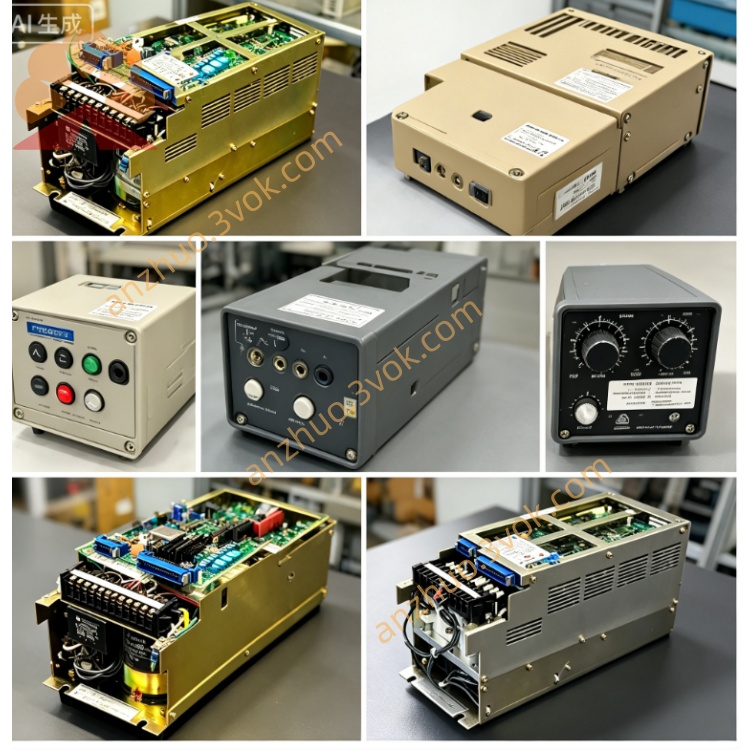
JANCD-JIF10
Description
I. Product Introduction
Brand: Yaskawa
Model: JANCD-JIF10 (Revision: -2)
Part Number: DF9202511-A
Series: YASNAC J300 (Complementary JCP10 main control board, JCP04/05/06 motion boards)
Function: Extended digital I/O interface board, providing more I/O points, supporting high-speed response and enhanced isolation
Alias: J300 I/F Expansion Board, High-speed I/O Baseboard
Core Purpose:
Suitable for I/O expansion of complex equipment such as machining centers, turning-milling composite machines, multi-axis machines, etc.
Processes multiple switch quantity signals such as emergency stop, limit stop, reference point, spindle orientation, tool magazine control, cooling / lubrication, etc.
Used in conjunction with JIF03, the maximum I/O expansion reaches 128 points, meeting the signal interaction requirements of large-scale machines.
Difference from JIF03:
JIF03: Standard I/O board (32 inputs / 32 outputs), basic response speed
JIF10: Extended I/O board (64 inputs / 64 outputs), high-speed response + enhanced isolation, suitable for complex working conditions
II. Technical Parameters
I/O Points: 64 digital inputs, 64 digital outputs (optical isolation, grouped isolation design)
Input Signals: DC24V active / passive compatible, response time ≤ 0.5ms, supports normally open / normally closed, with input filtering
Output Signals: DC24V/1A transistor output, maximum load 24W / point, overcurrent / short circuit protection, output status reading
Interface Terminals:
CN1: Input terminal panel (64 pins, divided into two groups)
CN2: Output terminal panel (64 pins, divided into two groups)
CN3: Backplane bus (40 pins, connects JCP10)
Bus Communication: J300 dedicated backplane bus, data throughput 100MB/s, supports real-time signal synchronization
Power Supply: DC24V (backplane power supply, power consumption approximately 25W)
Size / Weight: Approximately 245×210×35mm, weighs 2.5kg
Operating Environment: Temperature 0–55℃, humidity 30%–85% (no condensation), altitude ≤ 1500m
Isolation Voltage: I/O and system side AC2000V/1min insulation, enhanced anti-electromagnetic interference capability
LED Indicators: PWR (power), RDY (ready), ERR (fault), IN01–IN64 (input status), OUT01–OUT64 (output status)
III. Installation and Wiring
1. Installation
Power off and wait for capacitor discharge (≥5 minutes), anti-static operation (wear anti-static wristband).
Insert J300 cabinet expansion I/O slot (Slot 3), installed in parallel with JIF03 (Slot 2).
Push the board card evenly, tighten the upper and lower fixing screws (torque 1.0–1.5N·m).
Power on self-check: PWR constantly on, RDY flashing, ERR off, all input and output LED statuses normal.
2. Wiring
CN1 (input): Connect emergency stop, limit stop, reference point, tool magazine position, operation panel buttons, etc. DC24V signals.
CN2 (output): Connect spindle relay, cooling pump, lubrication pump, tool magazine motor, indicator lights, etc. DC24V load.
CN3 (backplane): 40-pin flat cable connects JCP10 main control board to achieve communication and power supply.
3. Wiring Points
Separate signal cables from power cables (spacing ≥ 30cm), avoid electromagnetic interference.
Input signal cables use shielded twisted pair, single-ended grounding (on the cabinet side). Output side of the load is equipped with a rectifier diode (for inductive loads) to protect the output transistor.
Do not plug or unplug the terminal panel and backplane cables while powered on to prevent damage to the board cards.
V. Maintenance and Care
1. Daily Maintenance (Monthly)
Dust Removal: Use dry compressed air (0.4–0.6MPa) to blow the surface of the board card, heat sinks, and gold fingers to remove dust and oil.
Visual Inspection: Check capacitors for no bulging, no leakage, no oxidation on solder joints, and no looseness or deformation of connectors.
Status Check: Observe LED indicators while powered on to confirm that PWR and RDY are normal and there is no ERR alarm.
2. Periodic Maintenance (Every 6 months)
Connector Tightening: Tighten all connection terminals and board card fixing screws to prevent poor contact.
Gold Finger Cleaning: Wipe the backplane gold fingers with isopropyl alcohol to remove the oxide layer and ensure stable communication.
Parameter Backup: Perform I/O parameter and PLC program backup to a USB drive through the system panel to prevent data loss.
3. Long-term Shutdown (>3 months)
Before power off, fully back up system data (parameters + programs + PLC).
Store the board card in a dry, dust-proof, and anti-static environment with humidity <60%.
Before reusing, perform a power-on preheating (2 hours), then connect the signal and load.
VI. Fault Troubleshooting
1. Common Fault Codes (displayed on the panel)
ALM20 (ERR constantly on): Backplane communication failure
Troubleshooting: CN3 cable connection, JCP10 power supply, backplane bus slot, gold finger oxidation.
ALM21 (ERR flashing): Input signal abnormal
Troubleshooting: DC24V power supply, terminal loosening, input filter parameters, sensor failure.
ALM22 (ERR slow flashing): Output load failure
Troubleshooting: Load short circuit, overload, rectifier diode damage, output transistor burnout.
ALM23 (ERR flashing 3 times): I/O configuration error
Troubleshooting: PLC program I/O address allocation, system parameter settings, and address conflict with JIF03.
2. No Input Response
Check if the DC24V voltage of the input signal is normal (fluctuation ≤ ±5%).
Measure the connection state of the input terminal and COM to confirm the signal is valid.
Clean the contacts of CN1 terminal panel and check if they are oxidized or loose.
Replace the JIF10 board card and confirm if the original board input circuit is damaged.
3. No Output Action
Check if the output load power supply is normal and the load circuit is not open.
Observe the output LED status to confirm that the system has issued an output command.
Measure the output terminal voltage to determine if it is a transistor open circuit or short circuit.
Check the output circuit fuse (if any), and determine if it has blown.
Get a Quote