
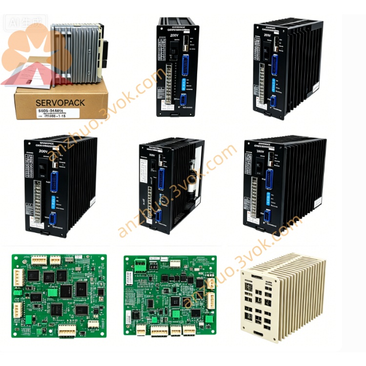
JANCD-IO01B
Description
I. Basic Introduction
Model: JANCD‑IO01B (often written as I0OIB)
Brand: Yaskawa (Anson)
Applicable: Motoman XRC robot control cabinet (XRC, ERC series)
Function: Signal interface between the robot and external devices (PLC, sensors, solenoids, safety doors, buttons)
Form: Standard slot-type PCB board, 2×50-pin connector (CN1 = input, CN2 = output)
II. Core Parameters (Easy to Understand)
Input: 40 points DC24V (NPN/PNP compatible)
Output: 40 points DC24V transistors
Each point maximum: 0.5A
Total current of the board: ≤1.5A
Power supply: DC24V ±10% (recommend using 2A fuse in series)
Response time: Input ≤1ms, Output ≤2ms
Operating temperature: 0~45℃ (inside the robot cabinet)
Board number: DF8000020 (part number for purchase)
III. Interfaces and Pins (Key) Connector
CN1 (50-pin): Input signals 1 to 40
CN2 (50-pin): Output signals 1 to 40
Each row has 50 pins, including common terminal (COM), 24V, 0V
Common terminal connection method (NPN/PNP)
NPN (commonly used): COM connected to 24V; 0V when there is a signal
PNP: COM connected to 0V; 24V when there is a signal
IV. Installation and Wiring Key Points (Core of the Manual)
1) Installation
Power off, anti-static (hand ring)
Insert into the dedicated slot of the control cabinet, with the gold fingers facing down
Fix with screws to avoid vibration and loosening
Keep away from power supplies (≥ 15cm) from frequency converters, contactors, etc.
2) Power connection
External DC24V connected to 24V and 0V of CN1/CN2
Series 2A fuse to prevent short circuit and board burnout
It is not recommended to use the internal 24V of the robot for large loads for a long time
3) Input wiring (sensors / buttons)
Use shielded twisted pair, single-ended grounding of the shield layer (at the board end)
NPN: Sensor output → Input point; COM → 24V
PNP: Sensor output → Input point; COM → 0V
4) Output Connections (Electromagnetic Valve / Relay)
Each point ≤ 0.5A; for heavy loads (> 0.5A), use an intermediate relay
Output point → Load → 0V (NPN)
Output point → Load → 24V (PNP)
V. Common Faults and Troubleshooting
Input no response: Check 24V, COM connection, sensor type (NPN/PNP), open circuit
Output does not operate: Check the load, connection, whether the output point is burned out, LED status
Communication error: Clean the gold fingers, replace the slot, check the backplane 5V
Board burnout: Mostly due to output short circuit, power supply reverse connection, overload
Get a Quote