
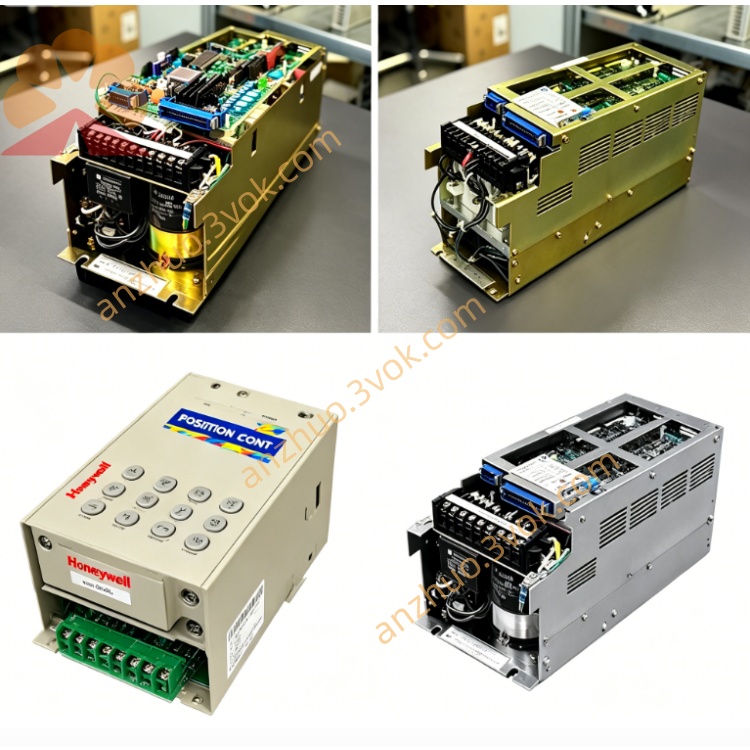
JANCD-G1R02
Description
Technical Specifications
Power Supply: Backplane bus 24V ±10%, power consumption approximately 22W
Communication Interface: Built-in remote I/O master station bus, RS-232/422/485, Ethernet (100Base-TX), I/O expansion interface
I/O Capacity: Supports expansion of up to 128 input points / 128 output points (remote slave module)
Transmission Distance: Maximum 500m for remote bus (shielded twisted pair), 100m for Ethernet
Transmission Rate: Remote bus 10Mbps, Ethernet 100Mbps
Environment: Operating temperature 0–55℃, storage temperature -20–70℃, humidity 10%–90% (no condensation)
Structure: 3U standard board card, metal shielding enclosure, weight approximately 0.6kg
Installation and Wiring
Vertically installed in the 3U idle slot of the control cabinet, leaving ≥50mm space for heat dissipation on top and bottom, fixed screws locked for vibration prevention. The metal enclosure is reliably connected to the cabinet ground (ground resistance ≤ 4Ω).
Internal: Power supply and system communication are automatically completed by the backplane bus, without internal strong current wiring.
External: Connect remote I/O slave module, Ethernet devices, serial peripheral devices, external I/O terminals; single-ended grounding of shielded lines, separation of strong and weak current wiring, spacing ≥ 10cm; remote bus and Ethernet use dedicated shielded lines, connector compression firmly.
Maintenance and Care
Daily observation of board card power supply, communication, and fault indicator light status, no bulging, burning, or peculiar smell on the board surface.
Quarterly: Use low-pressure dry compressed air to blow dust from the board card and slots, maintain good heat dissipation.
Every six months: Check the tightness of all plugs, terminals, capacitors, and solder joints, no aging, leakage, or retest the grounding continuity.
Long-term shutdown: Cut off the power supply, do dust and moisture protection; preheat for 30 minutes with no external equipment connected before restarting.
Fault Troubleshooting
No power indicator: Backplane DC24V power supply abnormal, board card fuse blown, power chip damaged; measure bus voltage, check fuse, replace board card for testing.
Remote communication interruption (light does not flash): Master station / slave station interface loose, communication chip failure, slave station module power-off; reinsert plug, measure interface signal, troubleshoot slave station power supply.
Ethernet: Network cable damaged, interface loose, IP conflict; replace network cable, reinsert interface, check IP parameters.
I/O signal no response: I/O terminal loose, optocoupler damaged, slave station module failure; check wiring, measure signal level, replace slave station module.
Data packet loss / error code: Poor shielding, interference from strong and weak current, unstable grounding; optimize wiring, reinforce grounding, replace shielded line.
Random error and system freeze: Chip short circuit, slot oxidation, excessive interference; clean slot, reinsert, replace board card for verification.
Get a Quote