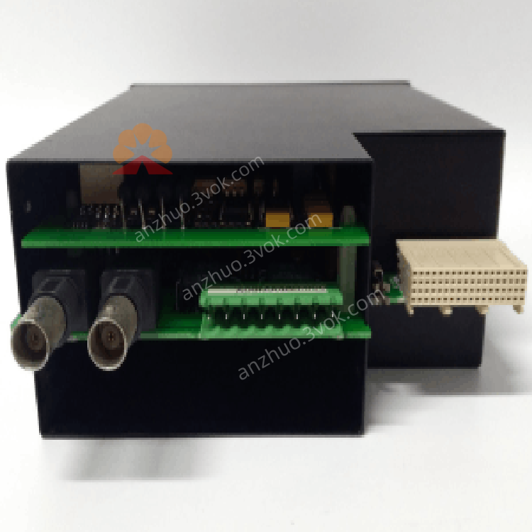
GE Multilin UR9EH UR Series Universal Relay CPU Module
Description
1. Product Overview


Key Features
High-Speed Processing: Powered by a 10 MHz 80188 processor with 1 MB RAM for efficient logic execution.
Universal Relay Compatibility: Works with all GE UR-series relays (G60, G30, L30, D30, etc.).
Advanced Logic Support: Executes complex protection algorithms, logic gates, latches, and timers.
Dual Communication Ports: Equipped with Ethernet (IEEE 1588) and RS-485 (Modbus RTU) for seamless system integration.
Plug-and-Play Installation: Hot-swappable design for easy replacement or upgrade without system shutdown.
Configurable Resources: Software-configurable via EnerVista UR software or local keypad/faceplate.
Industrial Hardening: Designed for high vibration, electrical noise, and extreme temperature environments.
2. Technical Specifications
2.1 General
| Parameter | Specification |
|---|---|
| Manufacturer | GE Multilin (General Electric) |
| Model | UR9EH |
| Type | CPU Module (Universal Relay Series) |
| Processor | 80188, 10 MHz |
| Memory | 1 MB RAM |
| Power Supply | 12–52 VDC |
| Current Draw | 2.8 A |
| Dimensions (W×H×D) | 145 × 72 × 125 mm (5.7 × 2.8 × 4.9 in) |
| Weight | Approx. 0.5 kg (1.1 lbs) |
2.2 Environmental
| Parameter | Specification |
|---|---|
| Operating Temperature | -20°C to +70°C (-4°F to 158°F) |
| Storage Temperature | -40°C to +85°C (-40°F to 185°F) |
| Relative Humidity | 5% to 95% (non-condensing) |
| Vibration | 0.2 mm displacement (5–10 Hz); 1 G (10–200 Hz) |
| Shock | 5 G (10 ms duration) |
| Protection Class | IP20 (front panel) |
2.3 Communication
| Interface | Protocol | Speed |
|---|---|---|
| Ethernet | IEEE 1588 (PTP) | 10/100 Mbps |
| RS-485 | Modbus RTU | Up to 115.2 kbps |
2.4 Compatibility
| Compatible Devices | Details |
|---|---|
| Relays | GE UR-series (G60, G30, L30, D30, UR60, UR80, UR100) |
| Configuration Tools | EnerVista UR Software, Local Keypad/Faceplate |
| I/O Modules | UR-series CT/VT, digital input/output modules |
3. Functional Description
3.1 Core Processing
3.2 Logic & Control
Logic Algorithms: Supports user-defined logic gates (AND/OR/NOT), latches, timers, and counters.
Protection Functions: Executes advanced protection schemes (e.g., motor/transformer differential, feeder protection).
Data Acquisition: Collects data from CT/VT modules, digital inputs, and communication ports for real-time monitoring.
3.3 Communication
Ethernet: Enables high-speed data exchange, IEC 61850 communication, and PTP time synchronization.
RS-485: Facilitates Modbus RTU communication with SCADA systems, HMI, or other PLCs.
Data Logging: Stores event records, fault data, and system logs for post-event analysis.
3.4 Resource Configuration
Server Scanning: Configurable to enable/disable IEC 61850 client/server functionality to optimize CPU usage.
Logic Mapping: Assigns logic inputs/outputs to physical I/O modules or communication points.
4. Installation & Wiring
4.1 Module Installation
Power Off: Shut down the UR-series relay and disconnect all power sources.
Slot Access: Open the relay’s front panel to access the CPU module slot.
Insert Module: Align the UR9EH with the slot guides and push firmly until fully seated.
Secure: Tighten the front-panel screws to ensure firm backplane contact.
Power On: Restore system power; check that the OK LED lights steadily (green).
4.2 Compatibility Note
The UR9EH must be paired with matching CT/VT modules (new CPU with new CT/VT modules, old CPU with old CT/VT modules) to avoid HARDWARE MISMATCH or DSP ERROR.
4.3 Communication Wiring
Ethernet: Connect a standard Ethernet cable to the front-panel Ethernet port; use for high-speed networking.
RS-485: Connect shielded twisted-pair cable to the RS-485 terminals; ground the shield at one end only.
Termination: Add 120 Ω termination resistors at the physical ends of the RS-485 bus.
5. Configuration
5.1 Software Requirements
EnerVista UR Software: v7.0 or later (for full configuration and monitoring).
Local Keypad/Faceplate: For basic configuration and status checks.
5.2 Configuration Steps
Connect: Use Ethernet or RS-485 to connect your PC (with EnerVista) to the UR9EH.
Detect Module: The software automatically detects the UR9EH and reads its current configuration.
Set Parameters:
Logic Configuration: Define protection algorithms, logic gates, and timers.
Communication: Configure IP address, Modbus slave address, and baud rate.
I/O Mapping: Assign logic inputs/outputs to physical modules or communication points.
Download: Transfer the configuration to the UR9EH; the module initializes and applies settings.
Verify: Check the OK LED (steady green) and communication status in EnerVista.
6. LED Indicators
| LED | Color | Status | Description |
|---|---|---|---|
| OK | Green | Steady On | Module powered, self-test passed, operational |
| OK | Green | Blinking | Self-test in progress or minor fault |
| OK | Off | — | No power or critical module failure |
| COM | Yellow/Green | Steady On | Communication ports active, no errors |
| COM | Yellow/Green | Blinking | Communication errors (e.g., noise, collision) |
| COM | Off | — | No communication activity or ports disabled |
7. Maintenance & Troubleshooting
7.1 Routine Maintenance
Visual Inspection: Check for loose cables, damaged connectors, or bent module pins.
LED Check: Verify OK (steady green) and COM (steady yellow/green) during normal operation.
Cleaning: Blow compressed air through ventilation slots to remove dust (power off first).
Configuration Backup: Regularly save and back up module configuration files via EnerVista.
7.2 Common Issues & Solutions
| Symptom | Possible Cause | Solution |
|---|---|---|
| OK LED Off | No power or module failure | Check relay power supply; reinsert module; replace if faulty |
| COM LED Blinking | Communication noise or incorrect wiring | Check cable shielding; verify termination resistors; confirm network settings |
| Logic Errors | Incorrect configuration or module mismatch | Review EnerVista settings; ensure UR9EH is paired with matching CT/VT modules |
| Module Not Recognized | Poor backplane contact or incompatible relay | Reinsert module; verify relay is a UR-series model (G60, G30, etc.) |
8. Ordering Information
Model: UR9EH
Description: GE Multilin UR Series CPU Module
Accessories:
UR-CBL-ETH: Ethernet cable (2 m)
UR-CBL-485: RS-485 cable (5 m)
UR-ACC-TERM: 120 Ω termination resistor kit
9. Compliance & Certifications
CE: Compliant with EU EMC and LVD Directives.
UL: UL 508 Listed for Industrial Control Equipment.
RoHS: Compliant with Restriction of Hazardous Substances.
IEC: Compliant with IEC 61131-2 (Programmable Controllers) and IEC 61850 (Substation Automation).
Get a Quote