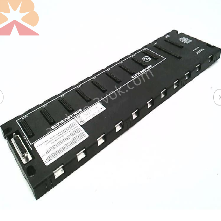
GE Fanuc IC693CHS391 Series 90-30 10-Slot CPU Baseplate
Description
1. Product Overview

Key Features
10-Slot Configuration: Dedicated slots for power supply, CPU, and 8 I/O/option modules.
Integrated Backplane Bus: High-speed parallel bus for logic control and data exchange.
Power Distribution: Supplies regulated +5VDC and +24VDC to all plugged-in modules.
Expansion Port: 25-pin D-sub connector for connecting expansion/remote baseplates.
Robust Construction: Industrial-grade design for high vibration and electrical noise environments.
DIN Rail or Panel Mount: Flexible mounting options for standard control cabinets.
2. Technical Specifications
2.1 General
| Parameter | Specification |
|---|---|
| Manufacturer | GE Fanuc (Emerson) |
| Series | Series 90-30 PLC |
| Model | IC693CHS391 |
| Type | CPU Baseplate (10 Slots) |
| Backplane Current | 420 mA @ 5 VDC |
| Backplane Rating | 10A |
| Dimensions (W×H×D) | 17.44 × 5.12 × 5.59 in (443 × 130 × 142 mm) |
| Weight | Approx. 3.5 lbs (1.6 kg) |
2.2 Environmental
| Parameter | Specification |
|---|---|
| Operating Temperature | 0°C to +60°C |
| Storage Temperature | -40°C to +85°C |
| Relative Humidity | 5% to 95% (non-condensing) |
| Vibration | IEC 61131-2 Compliant |
| Shock | Industrial Grade |
| Protection Class | IP20 (Front) |
2.3 Slot Definition
| Slot | Type | Purpose |
|---|---|---|
| Leftmost (Unnumbered) | Power Supply Slot | Dedicated for IC693PWR321/330 series power supply |
| Slot 1 (CPU/1) | CPU Slot | Dedicated for CPU module (e.g., IC693CPU364) |
| Slots 2–9 | I/O Slots | For digital/analog I/O, communication, or special modules |
3. Functional Description
3.1 Backplane Communication
3.2 Power Distribution
3.3 System Expansion
3.4 DIP Switch Configuration
4. Installation & Wiring
4.1 Mechanical Installation
DIN Rail Mounting:
Snap the baseplate onto a standard 35 mm DIN rail.
Secure with locking clips.
Panel Mounting:
Use four screws (M4) to fasten the baseplate to a flat surface.
Ensure adequate airflow (minimum 50 mm clearance around the unit).
4.2 Module Installation
Power Supply: Insert into the leftmost unnumbered slot and secure with screws.
CPU Module: Insert into Slot 1 (CPU/1) and tighten screws.
I/O Modules: Insert into Slots 2–9 according to the application requirements.
4.3 Expansion Cable Connection
Connect one end of the expansion cable to the 25-pin connector on the right side of the IC693CHS391.
Connect the other end to the expansion/remote baseplate.
Set the DIP switches on each baseplate to assign unique rack numbers.
5. Compatibility
5.1 Supported Modules
CPU Modules: All Series 90-30 CPUs (e.g., IC693CPU350, IC693CPU364).
Power Supplies: IC693PWR321, IC693PWR322, IC693PWR330.
I/O Modules: All Series 90-30 digital/analog I/O, communication, and special modules.
Expansion Baseplates: IC693CHS392 (5-slot), IC693CHS393 (10-slot remote).
5.2 System Limits
Max Baseplates: 7 (with CPU 350); 4 (with CPUs 331, 340, 341).
Max Distance (Expansion): 50 ft (15 m).
Max Distance (Remote): 700 ft (210 m).
6. LED Indicators
| LED | Color | Status | Description |
|---|---|---|---|
| PWR | Green | On | Baseplane power is normal |
| READY | Green | On | CPU is active and running |
| FAULT | Red | On/Blink | System error (power, backplane, or module fault) |
7. Maintenance & Troubleshooting
7.1 Routine Maintenance
Visual Inspection: Check for loose modules, damaged connectors, or signs of overheating.
Cleaning: Periodically blow compressed air through the ventilation slots to remove dust.
Connection Check: Verify all module and cable connections are secure.
7.2 Common Issues
| Symptom | Possible Cause | Solution |
|---|---|---|
| PWR LED Off | Power supply failure or loose | Check power supply module and input voltage |
| FAULT LED On | Defective I/O module or backplane error | Remove modules one by one to isolate the fault |
| No Expansion Communication | Loose cable or incorrect DIP switch setting | Check cable connection and rack number settings |
| Modules Not Recognized | Poor backplane contact | Remove and reinsert modules; check for bent pins |
8. Ordering Information
Model: IC693CHS391
Description: Series 90-30, 10-Slot CPU Baseplate
Accessories:
IC693CBL300: Expansion cable (3 m)
IC693CBL301: Expansion cable (5 m)
IC693ACC301: DIN rail mounting kit
9. Compliance & Certifications
CE: Compliant with EU EMC and LVD Directives.
UL: UL 508 Listed for Industrial Control Equipment.
RoHS: Compliant with Restriction of Hazardous Substances.
IEC: Compliant with IEC 61131-2 (Programmable Controllers).
Get a Quote