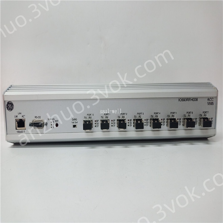
GE Fanuc IC690RFH008 8-Port Multimode Reflective Memory Hub
Description
1. Product Overview
2. Core Features
8 ST-type multi-mode fiber optic ports, full redundant loop topology
Transmission rate: 5 Mbps dedicated redundancy link bandwidth
Maximum single-node transmission distance: 2 km (multi-mode fiber)
Support hot backup redundant synchronization, fast fault switching
Standard 35mm DIN rail installation, compact and rugged structure
Strong anti-electromagnetic interference, adapt to severe industrial electromagnetic environment
Fully compatible with IC687RCM711 / IC687RCM711B redundant CPU series
Real-time link status monitoring, LED fault indication & rapid diagnosis
3. Technical Specifications
3.1 Electrical Parameters
| Item | Specification |
|---|---|
| Power Supply | 24 VDC ±10% |
| Power Consumption | ≤ 3.5 W |
| Electrical Isolation | Full optical isolation between ports |
3.2 Optical Parameters
| Item | Specification |
|---|---|
| Fiber Type | Multi-mode optical fiber |
| Connector | ST standard fiber connector |
| Number of Ports | 8 fiber channels |
| Baud Rate | 5 Mbps fixed redundancy rate |
| Max Transmission Distance | 2 km per link segment |
| Working Wavelength | 850 nm industrial optical wavelength |
3.3 Environmental Specifications
| Item | Specification |
|---|---|
| Operating Temperature | 0 °C ~ +60 °C |
| Storage Temperature | -40 °C ~ +85 °C |
| Humidity | 5% ~ 95% non-condensing |
| Protection Grade | IP30 indoor control cabinet grade |
| MTBF | ≥ 100,000 hours |
3.4 Mechanical Parameters
| Item | Specification |
|---|---|
| Mounting Mode | Standard 35mm DIN rail mounting |
| Dimensions | 120 × 85 × 55 mm |
| Weight | Approx. 320 g |
| Shell | Industrial flame-retardant metal + plastic composite shell |
4. System Installation & Wiring
4.1 Pre-installation Preparation
Completely cut off the power of PLC rack, redundant CPU and entire control system
Prepare qualified multi-mode ST fiber jumper, ensure fiber end face clean and undamaged
Confirm DIN rail is firmly fixed inside control cabinet, good grounding
4.2 Hardware Installation
Buckle IC690RFH008 hub firmly onto 35mm standard DIN rail
Connect fiber optic cables between redundant CPU redundancy ports and hub ports one by one
Build redundant ring network: connect each hub port in closed loop to realize dual-path backup
Fasten fiber connectors tightly, avoid bending, extrusion and large-angle folding of optical fiber
Connect 24VDC power supply to the module power terminal, confirm positive and negative polarity correctly
4.3 Redundancy Network Topology
Primary CPU ↔ IC690RFH008 Hub ↔ Standby CPU
Ring redundant architecture: single fiber link fault will not interrupt system communication
Automatically switch backup path within < 50ms when main link abnormal
5. Communication Protocols & Matching Devices
Bus Protocol: PACSystems internal redundant synchronization protocol, Genius system extended communication
Matching Host: IC687RCM711, IC687RCM711B redundant main control CPU
Matching System: RX3i PACSystems, VersaPAC redundant control platform
No additional protocol configuration required, plug-and-play after hardware networking
6. Panel LED Indicator Instructions
| LED Light | Status | Meaning |
|---|---|---|
| PWR (Green) | Always On | Normal power supply |
| PWR (Green) | Off | Power failure or abnormal power input |
| LINK (Green per port) | Always On | Fiber link connected normally |
| LINK (Green per port) | Blinking | Data transmitting & receiving |
| LINK (Green per port) | Off | Fiber disconnected / poor contact / link fault |
| ALM (Red) | On | Ring network broken, redundant path abnormal |
7. System Operation & Debugging
Power on the system sequentially: hub → redundant CPU → remote I/O rack
Wait 30s for CPU redundant synchronization to complete automatically
Check all LINK LEDs are on, no ALM alarm light
Test redundant switching: cut off main fiber link, confirm standby path takes over instantly
Verify CPU master-standby switchover function, ensure no program interruption or data loss
8. Maintenance & Troubleshooting
8.1 Daily Maintenance
Monthly: Inspect fiber connector tightness, clean dust on fiber end face
Quarterly: Check DIN rail fixation, power line contact status
Annual: Detect optical signal attenuation, replace aging fiber jumper regularly
8.2 Common Fault Handling
| Fault Phenomenon | Cause Analysis | Solution |
|---|---|---|
| LINK light off for single port | Fiber loose / broken / dirty end | Re-plug fiber; clean optical end face; replace jumper |
| ALM red light on | Ring network open circuit | Check all fiber links, repair broken path to restore closed loop |
| Redundancy cannot synchronize | Hub port mismatch / wrong topology | Rebuild ring network; check CPU redundancy parameter matching |
| PWR light off | 24V power loss / wrong polarity | Check power supply circuit; correct positive and negative wiring |
| Frequent link disconnection | Fiber excessive bending / electromagnetic interference | Standardize fiber layout; strengthen cabinet grounding |
9. Safety Specifications
Must disconnect all power before wiring, plugging and unplugging optical fiber to prevent electrostatic damage
Do not look directly at fiber optical emitter port, avoid damaging eyes by infrared light
Optical fiber cannot be bent sharply, bending radius ≥ 30mm
Install in sealed control cabinet, avoid dust, moisture and corrosive gas erosion
Reliably ground the module shell, reduce industrial electromagnetic interference
Do not operate beyond rated temperature range to avoid optical device aging failure
10. Warranty & Technical Support
Factory standard warranty period: 12 months from delivery date
Support firmware upgrade, network topology guidance and on-site fault diagnosis
After-sales service provided by Emerson GE Industrial Automation official channel
Get a Quote