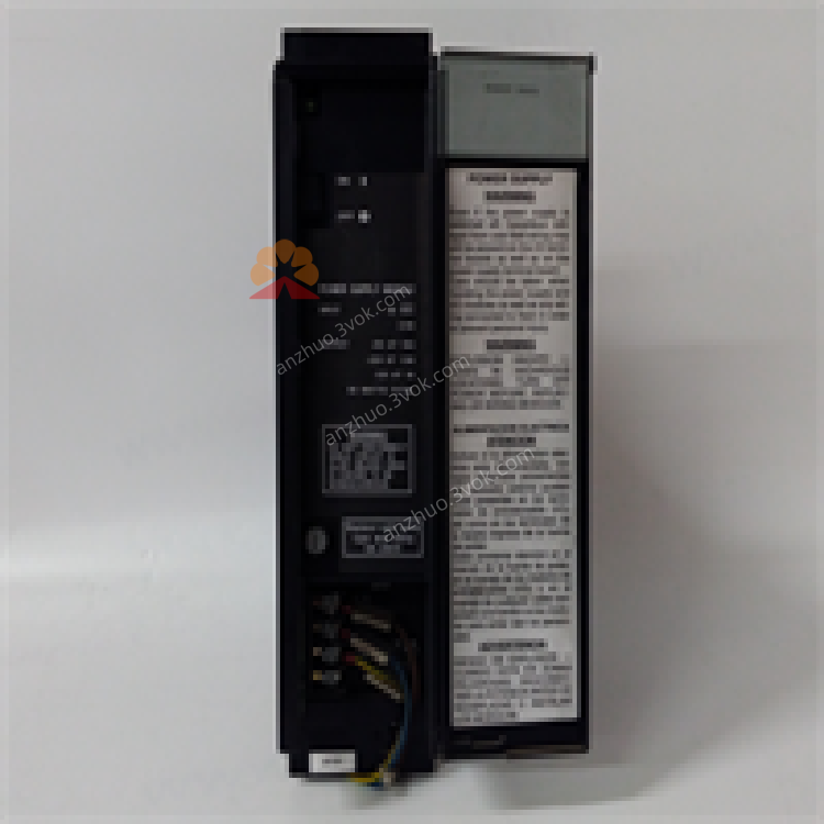
GE Fanuc IC697PWR748D Series 90-70 48VDC Rack Power Supply Module
Description
1. Product Overview

2. Key Features
Input: 35–60VDC (nominal 48VDC)
Outputs:
+5VDC @ 18A (logic power)
+12VDC @ 1.5A
–12VDC @ 1A
Total Power: 90W maximum
Dual‑rack capable: Feed a second rack via IC697CBL700 cable
Hot‑swap ready: Replace without system shutdown
Diagnostic LEDs: Power (green), Fault (red)
Protections: Overcurrent, short‑circuit, overvoltage (5V clamped at 6.7V)
Industrial grade: –10°C to +60°C operating, 5–95% non‑condensing humidity
3. Specifications
3.1 Electrical
| Parameter | Value |
|---|---|
| Nominal Input Voltage | 48VDC |
| Input Voltage Range | 35–60VDC |
| Max Input Power | 160W @ full load |
| Inrush Energy | 28J max @ 60VDC |
| Output Power | 90W max (all outputs) |
| +5VDC Output | 18A (min 1A load) |
| +12VDC Output | 1.5A max |
| –12VDC Output | 1A max |
| Ripple Noise | <60mV p‑p |
| Ride‑Through Time | ≥10ms |
3.2 Environmental
| Parameter | Value |
|---|---|
| Operating Temperature | –10°C to +60°C |
| Storage Temperature | –20°C to +85°C |
| Humidity | 5–95% non‑condensing |
| MTBF | 200,000 hours |
3.3 Mechanical
Dimensions: 170 × 150 × 30 mm
Weight: 1.2 kg
Mounting: Slide‑in, leftmost slot of 90‑70 rack (48‑pin backplane connector)
4. Installation
4.1 Rack Installation
Ensure the rack is powered off.
Insert the module into the leftmost slot of the Series 90‑70 rack.
Push firmly until the module clicks into place (secures to 48‑pin backplane connector).
Tighten the front panel screws (if equipped).
4.2 Dual‑Rack Configuration
Use IC697CBL700 pre‑wired cable.
Connect one end to the secondary power port on the IC697PWR748D.
Connect the other end to the power input port of the second 90‑70 rack.
Verify total load ≤ 90W; the second rack is limited to 5V power (<5.2A).
5. Wiring
5.1 Input Power Wiring
Confirm input voltage is 35–60VDC.
Connect the positive (+) input wire to the +48V terminal.
Connect the negative (–) input wire to the GND terminal.
Torque terminals to 0.8–1.0 N·m.
Use 14–18 AWG copper conductors.
5.2 Grounding
Connect the module’s chassis ground to the system’s protective earth (PE).
Ensure low‑impedance ground path for safety and noise reduction.
6. Operation
6.1 Power‑On
Apply input power (35–60VDC).
Check LEDs:
Green (Power): On = normal operation.
Red (Fault): Off = no faults; On = overvoltage, overcurrent, or short circuit.
Verify backplane voltages: +5V (±5%), +12V (±10%), –12V (±10%).
6.2 Normal Operation
The module provides continuous power to the backplane and I/O modules.
Monitor the Power LED for steady green; Fault LED should remain off.
In dual‑rack mode, ensure total load does not exceed 90W.
7. Protection & Diagnostics
7.1 Protection Features
Overcurrent: Electronic limiting on all outputs; shuts down if exceeded.
Short‑Circuit: Immediate shutdown and latched fault; reset by cycling input power.
Overvoltage: 5V output clamped at 6.7V; shuts down if input exceeds 60VDC.
7.2 LED Diagnostics
| LED State | Indication | Action |
|---|---|---|
| Green On, Red Off | Normal operation | None |
| Green Off, Red On | Fault (OV/OC/SC) | Cycle power; check wiring/load |
| Both Off | No input power | Check input voltage and wiring |
8. Maintenance
8.1 Regular Inspection
Monthly: Check wiring tightness, terminal corrosion, and LED status.
Quarterly: Clean dust from module surface and rack vents (use low‑pressure air).
Annually: Verify input/output voltages and load currents.
8.2 Troubleshooting
| Symptom | Possible Cause | Solution |
|---|---|---|
| No LEDs On | No input power | Check 48VDC supply and wiring |
| Red LED On | Overvoltage/overcurrent/short circuit | Remove load; cycle power; check for shorts |
| Intermittent Fault | Loose wiring/poor ventilation | Tighten terminals; clear vents |
| Dual‑Rack Not Powering | Cable fault/overload | Check IC697CBL700; reduce second rack load |
9. Warranty & Support
Warranty: 1‑year manufacturer’s warranty against defects.
Support: Contact GE Fanuc Emerson Automation for technical assistance.
10. Safety Precautions
Disconnect power before installation/wiring/maintenance.
Do not exceed maximum input voltage (60VDC).
Ensure proper grounding to prevent electric shock.
Operate within specified temperature range to avoid overheating.
Get a Quote