GE Fanuc IC697CMM742-LL Series 90-70 Type 2 TCP/IP Ethernet Communication Module
Description
1. General Description
1.1 Product Overview
1.2 Key Features
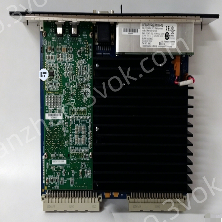
Triple Ethernet Ports: 10BaseT (RJ‑45), 10Base2 (BNC), and 15‑pin AUI; auto‑selects active port.
TCP/IP & SRTP: Native TCP/IP stack with GE SRTP for reliable host communication.
Ethernet Global Data (EGD): High‑speed producer/consumer data sharing between GE PLCs.
Multi‑Protocol Support: SNP, Modbus RTU (via serial), and IEEE 802.3/802.2 compliance.
Dual Serial Ports: RS‑232 (station management) and RS‑485 (firmware upgrade/debug).
Hot‑Swap Compatible: Install/remove without powering down the rack.
LED Status Indicators: Four LEDs for module, LAN, serial, and system status.
Firmware Upgradeable: In‑system updates via RS‑485 port.
Industrial Ruggedness: Conformal‑coated PCB; extended temperature range; IP20 rating.
2. Technical Specifications
2.1 Ethernet Interfaces
| Parameter | Specification |
|---|---|
| Ports | 10BaseT (RJ‑45), 10Base2 (BNC), AUI (15‑pin D‑sub) |
| Speed | 10 Mbps (IEEE 802.3 CSMA/CD) |
| Protocols | TCP/IP, SRTP, EGD, SNP |
| Network Media | 10BaseT (twisted pair), 10Base2 (thin coax), 10Base5 (thick coax), fiber (via AUI transceiver) |
| Port Selection | Automatic (one active port at a time) |
2.2 Serial Interfaces
| Port | Type | Baud Rate | Function |
|---|---|---|---|
| Station Mgr | RS‑232 (D‑sub 9) | 300–19,200 bps | Local diagnostics, commands |
| Software Load | RS‑485 (terminal block) | 300–19,200 bps | Firmware upgrades, configuration |
2.3 Electrical
| Parameter | Specification |
|---|---|
| Backplane Power | +5 VDC (max 2.0 A), +12 VDC (max 0.5 A) |
| Power Consumption | ≤10 W (typical) |
| Isolation | Ethernet/serial ports isolated from backplane |
2.4 Environmental & Mechanical
| Parameter | Specification |
|---|---|
| Operating Temperature | 0°C to +55°C (32°F to 131°F) |
| Storage Temperature | −40°C to +85°C (−40°F to +185°F) |
| Relative Humidity | 5%–95% (non‑condensing) |
| Altitude | Up to 2,000 m (derate >1,000 m) |
| Protection Class | IP20 (front) |
| Dimensions (H×W×D) | 124 mm × 36 mm × 152 mm (4.9” × 1.4” × 6.0”) |
| Weight | Approx. 0.3 kg (0.66 lb) |
| Rack Compatibility | IC697 Series racks (1 slot per module; up to 4 modules per CPU rack) |
3. Front Panel Layout
3.1 Connectors & Indicators
- Ethernet Ports
RJ‑45 (10BaseT): Twisted‑pair Ethernet connection.
BNC (10Base2): Thin‑coax Ethernet connection.
AUI (15‑pin D‑sub): For external transceivers (thick coax, fiber).
- Serial Ports
RS‑232 (D‑sub 9): Station management/debug.
RS‑485 (3‑pin terminal block): Firmware upgrade/configuration.
- LED Indicators (4)
MODULE OK: ON = Module initialized OK; OFF = Fault; Blinking = Diagnostics in progress.
LAN ONLINE: ON = Ethernet link active; Blinking = Data transfer; OFF = No link.
SERIAL ACTIVE: Blinking = Serial port activity; OFF = Inactive.
STATUS OK: ON = Normal operation; OFF = Warning/fault; Blinking = Maintenance mode.
- Reset Button
Functions: LED test, module restart, firmware load mode, maintenance mode.
4. Installation Instructions
4.1 Pre‑Installation
Power Off: Disconnect rack power before installation (hot‑swap supported for replacement).
Unpack & Inspect: Check for physical damage; verify connectors and LEDs.
Firmware Check: Confirm latest firmware version (upgrade via RS‑485 if needed).
4.2 Rack Mounting
Slot Selection: Install in any available slot of IC697 rack (1 slot per module; max 4 per CPU rack).
Insertion: Align module with rack guides; push firmly until backplane connectors fully seat.
Secure: Tighten front panel screws (torque: 0.8–1.0 N·m).
Grounding: Ensure rack chassis is connected to protective earth (PE).
4.3 Wiring & Connections
Ethernet: Connect cable to RJ‑45, BNC, or AUI (one port active at a time).
RS‑232: Connect D‑sub 9 cable to PC/HMI for diagnostics.
RS‑485: Wire terminal block for firmware upgrades (observe polarity).
Network Configuration: Set IP address, subnet mask, and gateway via programming software.
5. Configuration & Operation
5.1 Software Configuration
Programming Software: Use Logicmaster 90‑70 or Proficy Machine Edition.
IP Setup: Assign static IP (or enable DHCP) and subnet mask.
EGD Configuration: Define producer/consumer data exchanges between PLCs.
SRTP Setup: Configure host communication for programming/SCADA.
** Firmware Upgrade**: Connect PC to RS‑485 port; load latest firmware via software.
5.2 Operational Modes
Normal Operation: Module active; Ethernet/serial communication enabled.
Maintenance Mode: Enter via reset button; for diagnostics/firmware load.
Hot‑Swap: Replace module without power down; system auto‑reconfigures.
6. Maintenance & Troubleshooting
6.1 Preventive Maintenance
Cleaning: Every 3–6 months, use low‑pressure dry air to remove dust from ports/module.
Inspection: Check module seating, cable connections, and LED status.
Firmware Update: Annually check for latest firmware (upgrade via RS‑485).
6.2 Common Troubleshooting
| Symptom | Possible Cause | Solution |
|---|---|---|
| MODULE OK LED OFF | Backplane power fault; module hardware failure | Check rack power supply; reinsert module; replace if faulty |
| LAN ONLINE LED OFF | No Ethernet link; faulty cable; wrong port | Check cable/connector; verify active port (RJ‑45/BNC/AUI) |
| LAN ONLINE LED Blinking (No Data) | IP conflict; network misconfiguration; EGD/SRTP error | Verify IP settings; check network mask/gateway; reconfigure EGD/SRTP |
| SERIAL ACTIVE LED Not Blinking | Serial cable fault; wrong baud rate; no communication | Check cable; verify baud rate (300–19,200 bps) |
| STATUS OK LED OFF | Temperature fault; firmware error; configuration mismatch | Check ambient temperature; reflash firmware; verify configuration |
7. Safety & Compliance
7.1 Safety Warnings
Disconnect all power before servicing.
Do not open the module casing; no user‑serviceable parts inside.
Avoid moisture, dust, and corrosive gases.
Proper chassis grounding is required for safety and EMC.
7.2 Compliance Certifications
CE: EN 61000‑6‑2 (EMC), EN 61010‑1 (LVD).
UL: UL 508 (industrial control equipment).
CSA: CSA C22.2 No. 142.
RoHS: EU RoHS compliant.
8. Ordering Information
Model: IC697CMM742‑LL
Manufacturer: GE Fanuc (Emerson Automation)
Series: Series 90‑70 PLC
Standard Warranty: 12 months
Get a Quote