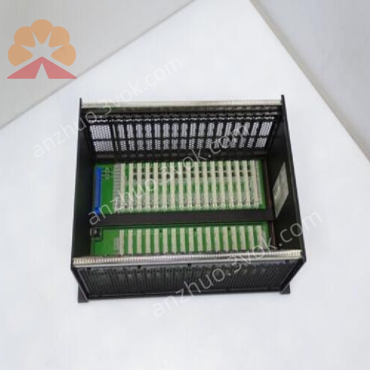
GE Fanuc IC698CHS117C PACSystems RX7i 17-Slot Chassis Backplane
Description
IC698CHS117C
1. General Information
1.1 Product Overview
1.2 Key Features
17‑slot configuration: 1 slot for power supply (Slot 0), 1 slot for CPU, 15 I/O slots; supports up to 8 double‑width modules.
VME64 backplane: 64‑bit, 4× bandwidth vs. standard VME; high‑speed I/O and memory transfers.
Front‑mount design: Panel/wall mount; easy access for installation and maintenance.
Hot‑swap capable: Modules can be inserted/removed under power (CPU/I/O).
Integrated cooling: Built‑in fan for forced air ventilation; maintains optimal operating temperature.
Wide compatibility: Supports RX7i CPU, Series 90‑70 I/O, and standard VME modules.
High reliability: Redundant power support; fault‑tolerant backplane design.
Industrial compliance: IP20, UL 508, IEC 60950‑1, CE marked.
2. Technical Specifications
2.1 Mechanical
| Parameter | Specification |
|---|---|
| Form Factor | 17‑slot front‑mount chassis |
| Dimensions (H×W×D) | 11.15 × 19.0 × 7.5 in (283 × 483 × 191 mm) |
| Weight | 10 kg (22 lb) approx. |
| Mounting | Panel/wall mount (front) |
| Slot Pitch | 0.8 in (20.3 mm) |
| Construction | Metal enclosure, IP20 |
2.2 Backplane & Slots
| Parameter | Specification |
|---|---|
| Backplane | VME64, 64‑bit, 32‑bit compatible |
| Total Slots | 17 |
| Slot 0 | Power supply (IC698PSAxxx series) |
| Slot 1 | CPU (IC698CPExxx series) |
| Slots 2–16 | I/O/communication (15 slots) |
| Module Width | Single or double width |
2.3 Power Distribution
| Parameter | Specification |
|---|---|
| Backplane Voltages | +5 VDC, +12 VDC, –12 VDC, +3.3 VDC (I/O) |
| Max Current (5 V) | 60 A |
| Max Current (12 V) | 12 A |
| Power Supply | RX7i power supply (Slot 0); redundant capable |
2.4 Environmental
| Parameter | Specification |
|---|---|
| Operating Temperature | 0 °C to +55 °C (derate >40 °C) |
| Storage Temperature | –40 °C to +85 °C |
| Relative Humidity | 5–95 % (non‑condensing) |
| Altitude | Up to 2000 m (derate >1000 m) |
| Cooling | Integrated fan, airflow: front to rear |
2.5 Compliance & Safety
UL 508: Industrial control equipment.
IEC 60950‑1: Information technology safety.
CE: EMC and LVD compliant.
RoHS: EU RoHS compliant.
3. Installation & Wiring
3.1 Mechanical Installation
Mounting Orientation: Install vertically (fan airflow front→rear) on a sturdy panel.
Clearance: Maintain ≥50 mm top/bottom/side clearance for ventilation.
Fasteners: Use M5 screws (4 corners); torque to 2.0–2.5 N·m.
Grounding: Connect chassis earth lug to protective earth (PE) for safety and EMC.
3.2 Module Installation
Power Supply (Slot 0): Insert IC698PSAxxx; secure front screws.
CPU (Slot 1): Insert RX7i CPU; tighten screws.
I/O Modules (Slots 2–16): Insert single/double‑width modules; ensure full backplane engagement.
Hot‑Swap: Modules may be inserted/removed with system power applied.
3.3 Wiring Guidelines
Power Wiring: Connect AC/DC to power supply (Slot 0) per supply manual.
I/O Wiring: Route field wiring to I/O module terminals; follow EMC practices (separate power/signal cables).
Shielding: Use shielded cables for analog/communication signals; terminate shields at both ends.
4. System Configuration
4.1 Slot Assignment
Slot 0: Power supply (required).
Slot 1: CPU (required).
Slots 2–16: I/O, communication, or specialty modules.
4.2 Redundancy Setup
Redundant Power: Install two chassis with redundant power supplies; configure via RX7i redundancy settings.
Redundant CPU: Use two chassis with synchronized CPUs for high availability.
4.3 Software Setup
Use Proficy Logic Developer – PLC Machine Edition to configure chassis, CPU, and I/O modules.
Configure backplane parameters, slot mapping, and redundancy.
5. Operation & Maintenance
5.1 Normal Operation
Power‑on: Apply power; check PSU and CPU LEDs for normal status.
LED Indicators:
PSU: “OK” = power good.
CPU: “RUN” = operating; “FAULT” = error.
Fan Operation: Verify fan runs on power‑on; check airflow.
5.2 Preventive Maintenance
Cleaning: Every 3–6 months: use low‑pressure dry air to clean fan and vents.
Inspection: Check module seating, screw tightness, and LED status.
Fan Replacement: If fan fails, replace with Emerson‑approved part.
5.3 Troubleshooting
| Symptom | Possible Cause | Action |
|---|---|---|
| No power | PSU fault; wiring loose | Check PSU input; tighten terminals |
| CPU fault | CPU not seated; backplane error | Reseat CPU; inspect backplane |
| Fan not running | Fan failure; power loss | Replace fan; check power |
| I/O module not detected | Module not seated; slot fault | Reseat module; test slot |
6. Safety Instructions
High Voltage: Hazardous voltages present when power is applied. Disconnect power before service.
No User Serviceable Parts: Do not open chassis or modules; refer to Emerson support.
Environmental: Avoid moisture, dust, and corrosive gases.
Grounding: Proper chassis grounding is required for safety and EMC.
7. Ordering Information
Model: IC698CHS117C
Manufacturer: Emerson (GE Fanuc)
Series: PACSystems RX7i
Warranty: 12 months standard
Get a Quote