31B075-503-4-00
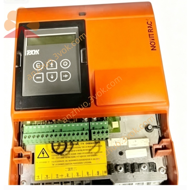
Description
1. Model Code Explanation
2. Main Electrical Parameters
Rated Output Power: 75 kW
Input Voltage: 3-phase AC 380~480 V
Rated Input Frequency: 50 Hz / 60 Hz
Rated Continuous Output Current: 150 A
Output Voltage Range: 0~480 V three-phase AC
Output Frequency Range: 0~400 Hz
Control Mode: V/F open-loop / Sensorless vector control
Overload Capacity: 150% rated current for 60 seconds, 125% long-term stable operation
Adjustable Switching Frequency: 2 kHz ~ 16 kHz
Full Load Power Factor: ≥0.95
Working Efficiency: ≥97%
Built-in Standard STO Safety Torque Off Function
3. Environmental and Physical Parameters
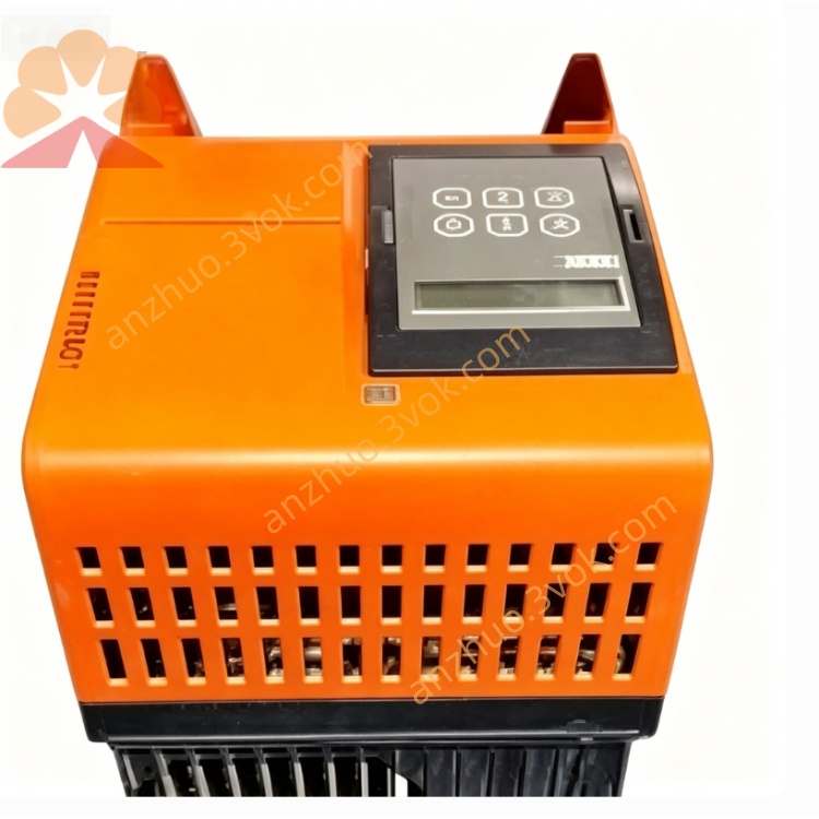
Protection Grade: IP20
Cooling Mode: High-power built-in fan forced air cooling
Working Ambient Temperature: 0°C ~ +45°C (full power output)
Storage Temperature: -25°C ~ +70°C
Working Humidity: 5%~95%, non-condensing
Installation Method: Vertical wall-mounted installation
Max Applicable Altitude: ≤1000m without power derating
Anti-vibration Grade: Suitable for heavy industrial vibration environment
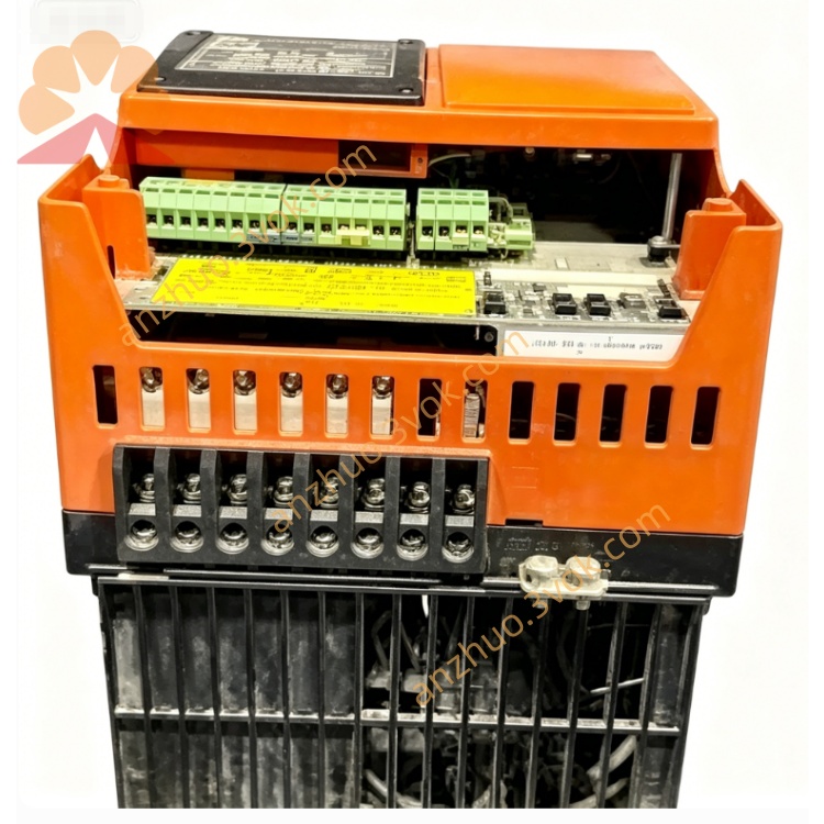
4. Standard External Control Interfaces
Onboard RS485 communication interface, support Modbus RTU protocol
Analog signal input: 0-10V DC / 0-20mA dual mode speed regulation
6 groups of programmable 24V DC digital input terminals
2 groups of programmable relay signal output terminals
Special PTC motor over-temperature protection access port
External braking resistor matching interface
Multi-segment fixed speed control terminals
Optional expansion communication module: Profinet, Profibus, Ethernet etc.
5. Core Operating Functions
Acceleration and deceleration time adjustable freely from 0.1s to 600s
Integrated dynamic braking and DC injection braking function for rapid stop
Intelligent energy-saving running mode, automatically optimize light-load operation efficiency
Three control modes: local panel control, external terminal control, remote communication control
High-precision slip compensation function to stabilize running speed under heavy load
Soft start and soft stop design, effectively reduce starting impact current and mechanical shock
Built-in closed-loop PID constant pressure and constant speed automatic control
Support one-click parameter copy, save and batch restore functions
Strong low-speed high-torque output performance
6. Complete Safety Protection Functions
Instantaneous overcurrent protection and thermal overload protection
System overvoltage and undervoltage fault protection
Three-phase input phase loss detection and protection
Inverter power module overheating protection
Electronic thermal motor overload protection
Output terminal short-circuit fault protection
Motor side ground fault protection
Running stall anti-blocking protection
Control terminal ESD anti-static protection
Hardware-level STO safety torque cut-off protection
7. Installation and Wiring Requirements
Cut off all power supply before wiring, debugging and maintenance
Main power circuit wires and control signal wires must be laid separately to avoid electromagnetic interference
Firmly connect the equipment PE grounding terminal to the factory unified grounding system
Reserve sufficient upper, lower and side ventilation heat dissipation space
Prohibit installation in dusty, humid, oil mist and strong corrosive gas sites
It is recommended to use shielded special frequency conversion motor cables for output wiring
Match suitable external braking resistors according to actual load working conditions
8. Standard Commissioning Steps
Check all wiring carefully to eliminate wrong connection and short circuit hidden dangers
Confirm that the on-site input power voltage matches the inverter rated voltage level
Accurately set motor nameplate parameters: rated voltage, rated current, rated frequency, rated speed
Select the corresponding operation control mode according to actual production needs
Set reasonable acceleration/deceleration time and upper/lower limit frequency
Conduct no-load trial operation first, confirm motor rotation direction and running sound
After stable no-load operation, gradually load and put into formal operation
9. Daily Maintenance Regulations
Clean internal dust and cooling fan dirt regularly every 3-6 months
Regularly check the fastening degree of all power terminals and control terminals
Monitor real-time running current and internal operating temperature during operation
Replace aging and abnormal noise cooling fans in time
All equipment failure inspection and maintenance must be operated by professional certified electricians
Get a Quote