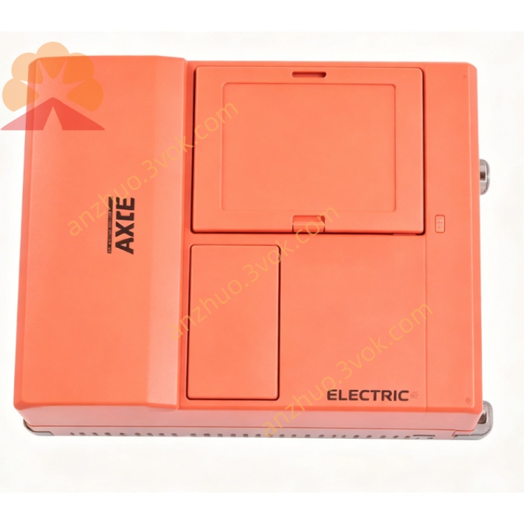
3108A-403-4-00
Description
1. Model Code Definition
3108A: Series & power rating – 31 = MOVITRAC 31 series, 08 = 7.5 kW, A = standard variant
403: Voltage class – 230 VAC (200–240 V)
4: Input type – 3‑phase AC
00: Standard firmware & hardware configuration
2. Electrical Ratings
Rated output power: 7.5 kW (3‑phase motor)
Input voltage: 3‑phase AC 200–240 V (nominal 230 V)
Input frequency: 50 Hz / 60 Hz
Rated output current: 34 A
Output voltage: 0–230 VAC, 3‑phase
Output frequency: 0–400 Hz
Control mode: V/F open‑loop (voltage‑to‑frequency)
Overload capacity: 150% / 60 s, 125% continuous
Switching frequency: 2–16 kHz (adjustable)
Power factor: ≥ 0.95 (at full load)
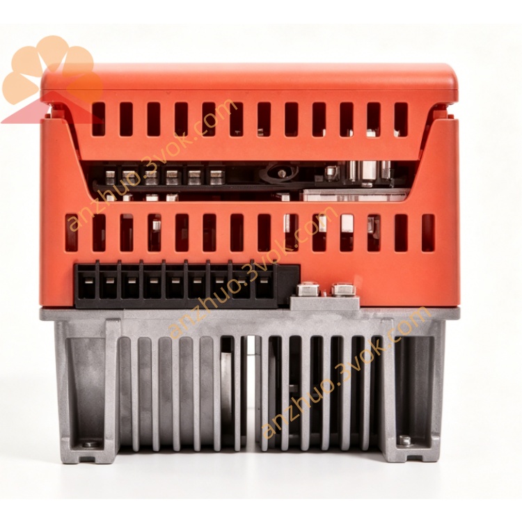
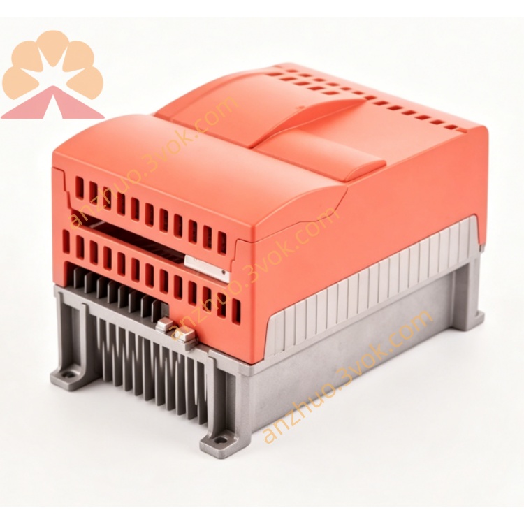
3. Mechanical & Environmental Data
Protection class: IP20 (front panel)
Cooling: Built‑in fan, vertical wall‑mounted
Ambient temperature: 0 °C … +45 °C
Storage temperature: −25 °C … +70 °C
Relative humidity: 5–95 %, non‑condensing
Altitude: ≤ 1000 m (no power derating)
Vibration resistance: 10–55 Hz, 0.15 mm amplitude
Dimensions (W×H×D): approx. 130 × 260 × 170 mm
Weight: approx. 4.5 kg
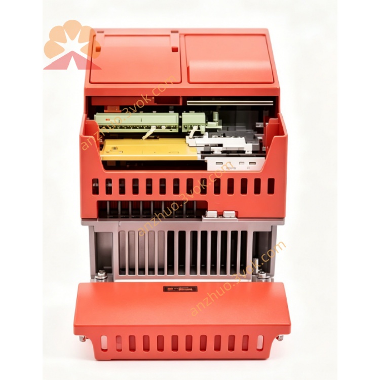
4. Standard Interfaces & Terminals
Communication: Onboard RS‑485 (supports Modbus RTU / SEW internal bus)
Analog input: 0–10 V DC (speed reference, 12‑bit resolution)
Digital inputs: 4 × programmable (24 V DC, sink/source)
Relay outputs: 1 × programmable (250 V AC / 30 V DC, 3 A)
Motor thermistor input: PTC/KTY (motor overheat protection)
Brake resistor connection: Internal dynamic braking unit (DBU)
Control terminals: Multi‑step speed, start/stop, forward/reverse, reset
5. Main Functions
Adjustable acceleration/deceleration: 0.1–600 s
Dynamic braking + DC injection braking: For rapid stop & holding
Energy‑saving mode: Automatic voltage reduction at light load
Control sources: Local keypad / external terminals / RS‑485 communication
Slip compensation: Improves speed accuracy under load
Soft start/soft stop: Reduces mechanical shock & inrush current
Built‑in PID controller: For constant pressure, flow, or speed
Multi‑step speed: Up to 8 preset speeds via digital inputs
Parameter copy: Save/load parameters via keypad or communication
6. Protection Features
Overcurrent (instantaneous & thermal)
Overvoltage / undervoltage
Input phase loss
Inverter overtemperature (IGBT & heatsink)
Motor overload (electronic thermal relay)
Output short circuit & earth fault
Stall prevention
Reverse polarity protection
ESD protection on control terminals
7. Installation & Wiring
7.1 Mechanical Installation
Mount vertically on a flat, vibration‑free surface
Keep ≥ 100 mm clearance above and below for airflow
Avoid direct sunlight, dust, oil mist, and corrosive gases
7.2 Electrical Wiring
Power cables: Use 4‑core shielded cables (L1/L2/L3/PE)
Motor cables: Shielded, 3‑phase + PE, max length 50 m
Control cables: Twisted pair, shielded, separate from power cables
Grounding: Connect PE terminal to main earth (≤ 4 Ω)
Brake resistor: Connect to DBU terminals (optional, for high inertia loads)
8. Commissioning Steps
Pre‑check: Verify wiring, voltage, and motor nameplate data
Power‑on: Display shows “rdy” (ready)
Motor parameter setting:
Rated voltage (230 V)
Rated current (match motor)
Rated frequency (50/60 Hz)
Rated speed
Control mode selection: Terminal / Keypad / Communication
Accel/decel time setting: 5–10 s (typical)
No‑load test: Run motor at 50 Hz, check direction & noise
Load test: Gradually apply load, monitor current & temperature
Save parameters: Write settings to non‑volatile memory
9. Maintenance
Regular cleaning: Every 3–6 months, clean fan & heatsink
Terminal check: Tighten power & control terminals annually
Fan replacement: If noisy or failed (use original SEW part)
Insulation test: Every 2 years (disconnect motor first)
Firmware update: Via RS‑485 (use SEW software)
10. Compliance & Standards
CE marking (Low Voltage Directive 2014/35/EU)
EMC compliant (EN 61800‑3, Category C2)
RoHS compliant (2011/65/EU)
UL 508C (optional)
ISO 9001 certified manufacturing
11. Application Examples
Conveyors & material handling
Fans & pumps (energy‑saving speed control)
Textile machinery
Packaging machines
General‑purpose industrial drives
Get a Quote