3007-403
Description
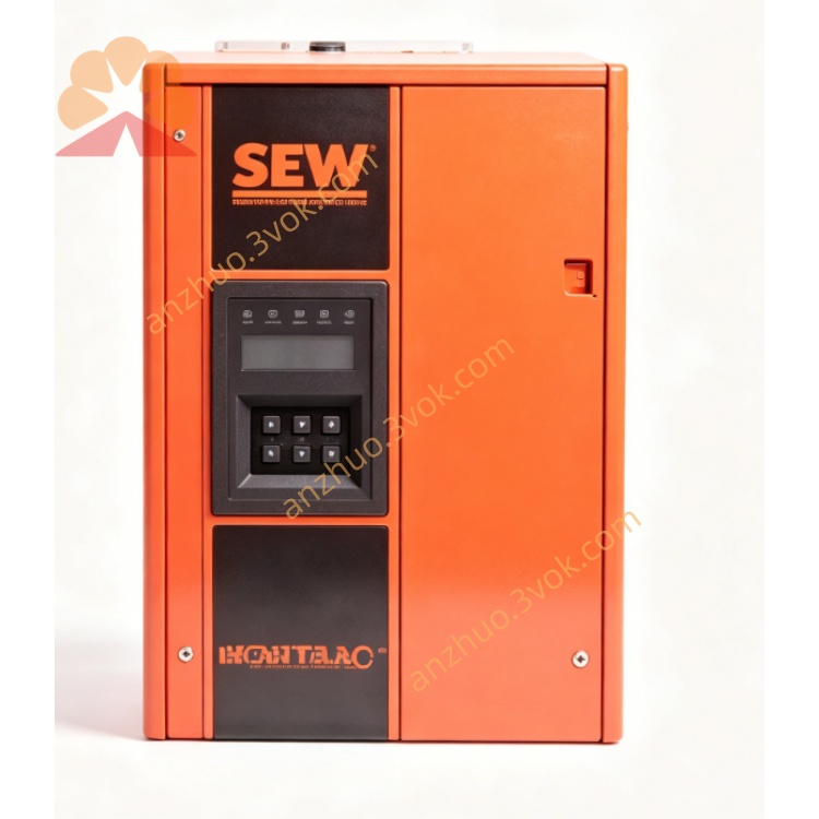
1. Model Code Definition
2. Electrical Parameters
Rated Power: 22 kW
Input Voltage: 3-phase AC 200~240 V (Nominal 230 V)
Input Frequency: 50 / 60 Hz
Rated Output Current: 85 A
Output Voltage Range: 0 ~ 230 V 3-phase AC
Output Frequency Range: 0 ~ 400 Hz
Control Mode: V/F open-loop control
Overload Capacity: 150% rated current for 60 seconds
Switching Frequency: Adjustable
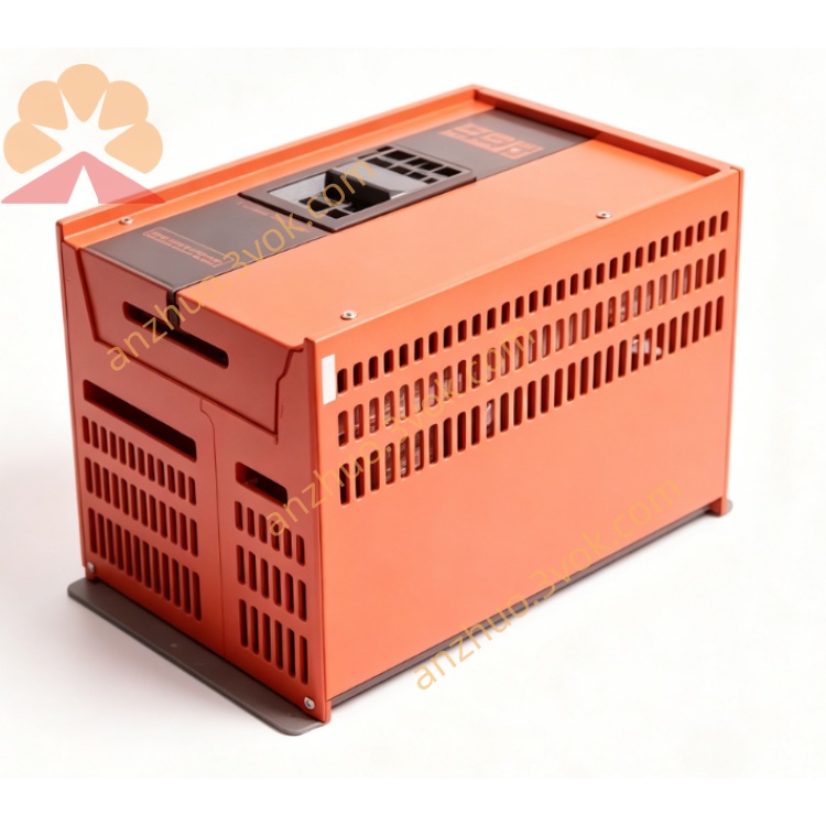
3. Physical & Environmental Data
Protection Class: IP20
Cooling Mode: Forced air cooling with built-in fan
Operating Temperature: 0 °C ~ +45 °C
Storage Temperature: -25 °C ~ +70 °C
Relative Humidity: 5% ~ 95%, non-condensing
Installation Method: Vertical wall mounting
Max Altitude: ≤1000m without power derating
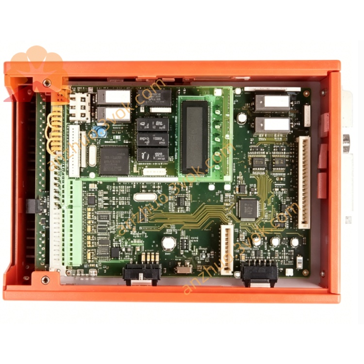
4. Standard Interfaces
Built-in RS485 communication interface
Multiple digital input and relay output terminals
0-10V analog speed reference input
Multi-step speed control terminals
PTC motor over-temperature detection interface
Integrated dynamic braking unit interface
5. Main Functions
Adjustable acceleration and deceleration time
Fast stop via dynamic braking and DC braking
Energy saving operation mode
Support panel control, terminal control and remote communication control
Slip compensation for steady speed operation
Soft start and soft stop to reduce mechanical impact
Built-in PID constant pressure and constant speed control
6. Complete Protection Functions
Over current protection
Over voltage & under voltage protection
Input phase loss protection
Inverter overheating protection
Motor overload electronic thermal protection
Output short circuit protection
Earth fault protection
Stall prevention protection
7. Installation & Wiring Requirements
Cut off power supply before all wiring and maintenance work
Separate power cables and control cables to avoid signal interference
Connect reliable PE protective ground wire strictly
Reserve sufficient ventilation space for heat dissipation
Keep away from dusty, humid, corrosive gas and strong vibration areas
Use shielded dedicated motor cables for motor connection
8. Commissioning Guidelines
Check all wiring to confirm no wrong connection and short circuit
Confirm input power voltage matches inverter rated voltage
Set motor rated voltage, current and frequency parameters
Select suitable control mode according to site requirements
Conduct no-load trial operation firstly
Put into formal load operation after stable running
9. Daily Maintenance
Regularly clean cooling fan and internal dust
Periodically check terminal connection tightness
Monitor real-time running current and temperature
Replace damaged cooling fans timely
Professional electricians only for fault inspection and repair
10. Application Scope
11. Compliance Standards
Get a Quote