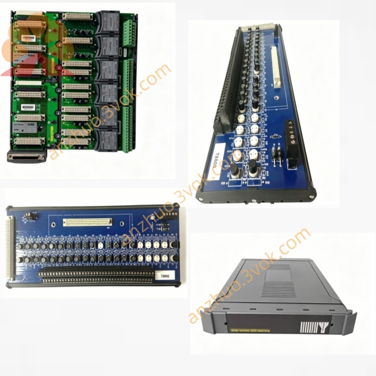
ICS Triplex T8846 Speed Monitor Input FTA Terminal Assembly for Trusted TMR SIL3 SIS Safety System
Description
1. Introduction
Function: Speed monitor input field termination & conditioning (SIFTA)
Channels: 9 speed input channels (3 groups × 3 channels)
Sensor Types: Passive magnetic/inductive; active open‑collector; active totem‑pole
Signal: Pulse/frequency input (speed), isolated per group
Safety: SIL 3 (with T8442), CE, UL, CSA, ATEX, IECEx
Isolation: Group‑to‑group & field‑to‑system galvanic isolation
Mounting: Standard DIN rail
Operating Temp: –40 °C to +70 °C (harsh environment rated)
2. Product Overview
3 sensor groups (×3 channels): Independent power and isolation per group for fault containment.
Multi‑sensor compatibility: Works with passive magnetic pickups (no external power), active open‑collector, and active totem‑pole sensors (field‑powered).
Field‑replaceable fuses: Per‑group and per‑channel fuses, replaceable in situ.
Galvanic isolation: 2500 VDC between groups; field side isolated from T8442 system side.
LED diagnostics: Per‑channel and per‑group status LEDs for power, signal, and fault indication.
SIL 3 certified system: When paired with T8442, meets IEC 61508 SIL 3 for overspeed/underspeed protection.
Turbine overspeed/underspeed protection (steam/gas turbines)
Compressor and pump speed monitoring
Generator shaft speed & phase reference
Critical rotating machinery ESD interlocks
Burner management system (BMS) fuel pump speed validation
3. Specifications
3.1 Mechanical
Form Factor: DIN‑rail mount enclosure (compact, industrial grade)
Dimensions (H × W × D): 102 mm × 391 mm × 127 mm
Weight: Approx. 0.75 kg
Mounting: Standard 35 mm DIN rail (horizontal)
Termination: Screw terminals (field sensors); ribbon cable to T8442
Protection: IP20 (enclosed), conformal coated PCB (T8846C available)
3.2 Electrical
System Interface: Ribbon cable to T8442 TMR speed monitor module
Field Sensor Groups: 3 independent groups (G1, G2, G3), 3 channels each (CH1–CH9)
Sensor Types & Input Ranges:
Passive magnetic/inductive: 20 mV–30 Vpp, 1 Hz–20 kHz
Active open‑collector: 5–24 VDC, sinking, 1 Hz–20 kHz
Active totem‑pole: 5–24 VDC, sourcing/sinking, 1 Hz–20 kHz
Field Supply (Active Sensors): 24 VDC ±10 %, per group isolated, 50 mA max per group
Isolation: 2500 VDC (group‑to‑group); 2500 VDC (field ↔ T8442 system)
Fusing: Per‑channel (100 mA); per‑group (500 mA), field‑replaceable
Surge Protection: TVS diodes per channel (±30 V)
Signal Conditioning: Schmitt trigger, low‑pass filter (20 kHz), level shifting
Power Consumption: ≤ 15 W (all groups active)
3.3 Functional
Redundancy: TMR system (via T8442); FTA provides 3‑way signal splitting
Channel Mapping: 9 inputs → T8442 9‑channel TMR speed monitor
Diagnostics:
Per‑channel signal presence (LED)
Per‑group power healthy (LED)
Fuse fault indication (per group)
Short circuit protection (per channel)
Open sensor detection (active sensors)
Response Time: ≤ 1 ms (sensor pulse to T8442 input)
Fault Tolerance: Single‑channel/group fault does not affect other groups or TMR voting
3.4 Environmental
Operating Temperature: –40 °C to +70 °C
Storage Temperature: –40 °C to +85 °C
Humidity: 5–95 % RH, non‑condensing
Vibration: 10–57 Hz ±0.15 mm; 57–150 Hz 2.0 g
Shock: 30 g, ½ sine wave, 11 ms
Hazardous Area: ATEX / IECEx Ex ia IIC T4 Ga (with external barriers)
3.5 Safety & Certification
Safety Standard: IEC 61508 SIL 3 (system with T8442, TÜV Certified)
Approvals: CE, UL, CSA, ATEX, IECEx, FM
Fault Tolerance: TMR 3‑2‑0 (system level); FTA provides isolated group redundancy
PFHd: < 5.0 × 10⁻⁹ / hour (system with T8442)
4. Front Panel Indicators
PWR G1/G2/G3 (Green): ON = group power healthy
CH1–CH9 (Yellow): Flashing = pulse signal present; OFF = no signal/fault
FUSE G1/G2/G3 (Red): ON = group fuse blown
5. Installation
Mounting: Attach to standard 35 mm DIN rail in control cabinet (horizontal)
Orientation: Keep vents clear; allow 50 mm clearance top/bottom for airflow
Cabling: Route field sensor cables away from high‑power AC cables (EMI avoidance)
System Connection: Connect ribbon cable from T8846 to T8442 module in T8100/T8400 chassis
Environmental Note: Use T8846C (conformal coated) for > 85 % RH, salt mist, or corrosive vapor environments
6. Wiring
Passive Magnetic/Inductive Sensors: Connect to CHx terminals (no external power)
Active Open‑Collector Sensors: Connect to CHx + 24 VDC (group supply)
Active Totem‑Pole Sensors: Connect to CHx + 24 VDC (group supply)
Field Power: 24 VDC ±10 % to G1/G2/G3 power terminals (isolated per group)
Shielding: Sensor cable shields grounded at T8846 only (single‑point grounding)
Wire Gauge: 18–24 AWG, twisted pair, shielded for speed signals
7. Ordering Information
T8846: Standard Speed Monitor Input FTA (SIFTA), –40 °C to +70 °C
T8846C: Conformal coated Speed Monitor Input FTA (harsh environments)
T8442: TMR Speed Monitor Module (Trusted T8000 chassis)
T8100 / T8400: Trusted system chassis
T8840: Standard 40‑channel analog output FTA (for reference)
Get a Quote