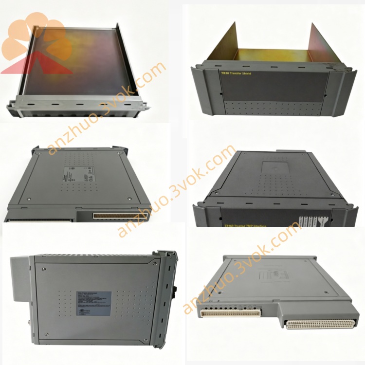
ICS Triplex T8444 Digital Field Terminal Assembly FTA Board for Trusted TMR SIL3 SIS Safety System
Description
1. Introduction
Function: TMR pulse generation + stepper motor control + position monitoring
Motors: 2 independent stepper motors (damper rod actuators)
Control: Bi‑directional fast/slow movement, emergency stop, hold
Feedback: Rod position (%) + thyristor driver status
Safety: IEC 61508 SIL 3 (TÜV)
Architecture: 3‑2‑0 TMR (Hardware Implemented Fault Tolerance)
Isolation: 2500 VDC opto/galvanic isolation
ESD: Rod release on safety demand
Hot‑swap: Supported (Companion Slot / SmartSlot)
2. Product Overview
2‑channel TMR pulse generator for stepper motors (damper rods)
Bi‑directional fast/slow motion profiles (configurable)
Emergency stop (E‑stop) and position hold functions
Rod position feedback (0–100% movement)
Thyristor driver fault detection (open/short/mismatch)
ESD‑initiated rod release (safety demand)
2500 VDC opto/galvanic isolation (field ↔ system)
TMR diagnostics + triplicated BIST (per channel)
Front‑panel LED status (module + motors + faults)
Hot‑swap & hot‑standby (companion slot)
3. Specifications
3.1 Mechanical
Form Factor: T8000 chassis single‑width module, 6U height
Dimensions (H × W × D): 266 mm × 31 mm × 303 mm
Weight: Approx. 1.2 kg
Mounting: T8100 / T8400 chassis slots 1–16
Termination: Custom FTA for thyristor drivers + position sensors
3.2 Electrical
System Supply: 20–32 VDC (nominal 24 VDC)
Power Consumption: ≤ 20 W
Pulse Outputs: TMR‑triplicated pulse trains (5–24 VDC)
Output Current: ≤ 20 mA per channel
Position Inputs: Analogue/digital feedback (0–10 V / 4–20 mA)
Isolation: 2500 VDC opto/galvanic (field to backplane)
Overcurrent Protection: Per‑channel automatic (fuse‑less)
3.3 Functional
Redundancy: TMR (3 independent slices, 3‑2‑0 fault tolerance)
Motor Control: 2 × stepper motors (bi‑directional, fast/slow)
Position Range: 0–100% (rod movement)
Response Time: ≤ 10 ms (motion command)
Diagnostics:
Thyristor driver open/short circuit
TMR pulse mismatch
Position drift / range fault
On‑board BIST (periodic self‑test)
ESD Action: Rod release on safety signal
SOE Resolution: 1 ms (position events + faults)
3.4 Environmental
Operating Temperature: –20 °C to +60 °C
Storage Temperature: –40 °C to +85 °C
Humidity: 5–95 % RH, non‑condensing
Vibration: 10–57 Hz ±0.075 mm; 57–150 Hz 1.0 g
Shock: 15 g, ½ sine wave, 11 ms
3.5 Safety & Certification
Safety Standard: IEC 61508 SIL 3 (TÜV Certified)
Approvals: CE, UL, CSA, ATEX, IECEx
Fault Tolerance: TMR 3‑2‑0
PFHd: < 1.0 × 10⁻⁹ / hour (SIL 3)
4. Front Panel Indicators
PWR (Green): ON = module power healthy
RUN (Green): ON = active; FLASHING = BIST/initialization
FAULT (Red): ON = critical fault; FLASHING = minor fault
COM (Green): FLASHING = backplane communication active
M1/M2 LEDs: Motor 1/2 status + position/fault indication
5. Installation
Chassis: Insert into any vacant slot in T8100 / T8400 chassis
Hot‑Swap: Supported (Companion Slot / SmartSlot)
Front‑Panel Screws: Torque 0.8–1.0 Nm
Termination: Connect to custom FTA for thyristor drivers and position sensors
6. Wiring
Pulse Outputs: To thyristor drivers (24 VDC pulses)
Position Feedback: From rod sensors (4–20 mA / 0–10 V)
ESD Input: From safety system (dry contact)
Wire Gauge: 16–22 AWG stranded
Terminal Torque: 0.5–0.6 Nm
7. Operation
Power‑Up: PWR ON; RUN flashes during BIST (5–10 s)
Normal: PWR/RUN steady green; FAULT OFF; COM flashing
Motion: M1/M2 LEDs indicate direction/speed
Faults:
FAULT ON: TMR mismatch, driver fault, position error
FAULT FLASHING: Single‑slice fault, minor mismatch
ESD: Triggers immediate rod release (safety state)
SOE: All position changes, faults, and ESD events time‑stamped at 1 ms
8. Ordering Information
T8444: Standard TMR pulse generator (–20 °C to +60 °C)
T8444C: Conformal coated (harsh environment)
Custom FTA: Thyristor driver + position sensor termination assembly
T8100 / T8400: Trusted chassis
Get a Quote