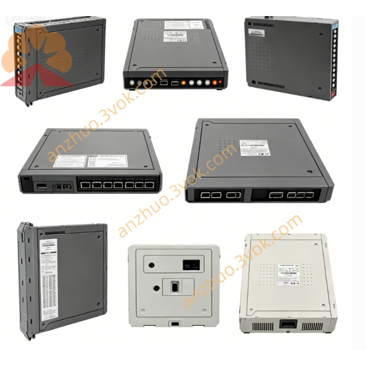
ICS Triplex T8433 Analog Field Terminal Assembly FTA Board for Trusted TMR SIL3 SIS Safety System
Description
1. Introduction
Function: 20‑channel isolated analogue input (4–20 mA)
Architecture: Fully triplicated TMR (3‑2‑0 fault tolerant)
Safety: IEC 61508 SIL 3
Inputs: 4–20 mA (per‑channel configurable)
Resolution: 12‑bit (1 part in 4096)
Isolation: 2500 VDC optical/magnetic 2‑stage galvanic isolation
SOE: 1 ms time‑stamp resolution
Hot‑swap: Supported
Diagnostics: Per‑channel open/short/range fault detection
2. Product Overview
20 channels isolated 4–20 mA analogue input
Triple Modular Redundancy (TMR) with HIFT architecture
Per‑channel open/short‑circuit and over/under‑range detection
2500 VDC optical/magnetic 2‑stage galvanic isolation
1 ms resolution SOE logging
Hot‑swap capable (Companion Slot / SmartSlot)
Front‑panel LED status indicators (module + per‑channel)
Compatible with T8100 / T8400 chassis
High accuracy: 0.2% of span (25 °C)
3. Specifications
3.1 Mechanical
Form Factor: T8000 chassis single‑width module, 6U height
Dimensions (H × W × D): 241 mm × 30 mm × 300 mm
Weight: Approx. 1.13 kg
Mounting: T8100 / T8400 chassis slots 1–16
Terminals: Front‑panel screw terminals (20 channels)
3.2 Electrical
System Supply: 20–32 VDC (nominal 24 VDC)Rockwell Automation
Power Consumption: ≤ 15 W
Input Range: 4–20 mA (configurable for 0–20 mA)
Resolution: 12‑bit (1 part in 4096)
Accuracy: 0.2% of span (25 °C)
Temperature Drift: 50 ppm/°C
Isolation: 2500 VDC optical/magnetic 2‑stage galvanic isolation
Channel Crosstalk: –40 dB typical
Update Time: ≤ 1 ms per channel
Field Loop Supply: External (loop‑powered)
3.3 Functional
Redundancy: TMR (three independent slices)
Voting: 1oo2D per channel
Diagnostics:
Open‑circuit detection
Short‑circuit detection
Over‑/under‑range detection
On‑board BIST (periodic self‑test)
SOE Resolution: 1 ms
SOE Accuracy: ±0.5 ms
Response Time: ≤ 2 ms
Filtering: Configurable 50 Hz / 60 Hz rejection or fast response
3.4 Environmental
Operating Temperature: –5 °C to +60 °C
Storage Temperature: –25 °C to +70 °CRockwell Automation
Humidity: 5–95 % RH, non‑condensing
Vibration: 10–57 Hz ±0.075 mm; 57–150 Hz 1.0 g
Shock: 15 g, ½ sine wave, 11 ms
3.5 Safety & Certification
Safety Standard: IEC 61508 SIL 3
Approvals: CE, UL, CSA, ATEX, IECEx
Fault Tolerance: TMR (3‑2‑0)
PFHd: < 1.0 × 10⁻⁹ / hour (SIL 3)
4. Front Panel Indicators
PWR (Green): ON = module power healthy
RUN (Green): ON = active; FLASHING = BIST/initialization
FAULT (Red): ON = critical fault; FLASHING = minor fault
COM (Green): FLASHING = backplane communication active
CH1–CH20 LEDs: Reflect input status / fault per channel
5. Installation
Chassis: Insert into any vacant slot in T8100 / T8400 chassis
Hot‑Swap: Supported (Companion Slot / SmartSlot)
Front‑Panel Screws: Torque 0.8–1.0 Nm
6. Wiring
Signal Type: 4–20 mA current loop
Field Connection:
Transmitter + → channel +
Transmitter – → channel –
Wire Gauge: 16–22 AWG stranded
Terminal Torque: 0.5–0.6 Nm
7. Operation
Power‑Up: PWR ON; RUN flashes during BIST (5–10 s)
Normal: PWR/RUN steady green; FAULT OFF; COM flashing
Faults:
FAULT ON: TMR mismatch, short circuit, overrange
FAULT FLASHING: Single‑path fault, minor mismatch
SOE: All analogue threshold crossings time‑stamped at 1 ms
8. Ordering Information
T8433: Standard 20‑ch TMR 4–20 mA input (–5 °C to +60 °C)
T8833: Field Termination Assembly (FTA)
TC‑T8433: Terminal cable kit
T8100 / T8400: Trusted chassis
Get a Quote