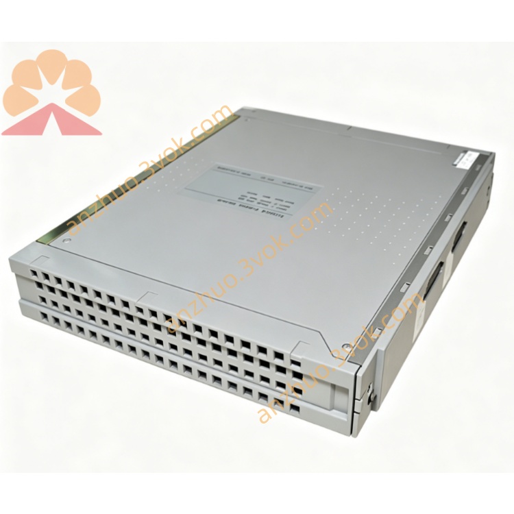
ICS Triplex T8225 Trusted Power Supply Module for SIL3 TMR Safety System
Description
Architecture: TMR‑compatible, dual redundant inputs/outputs, current sharing
Safety: IEC 61508 SIL 3, TÜV certified
Hot‑Swap: Online replacement without system shutdown
Power Rating: 250 W continuousRockwell Automation
Hold‑up Time: ≥20 ms (bridges brief input interruptions)Rockwell Automation
2. Specifications
2.1 Electrical
Input Voltage (Redundant):
AC: 100–120 V AC / 200–240 V AC, 50/60 Hz
DC: 24 V DC (20–32 V DC range)
Output Voltage: +24 V DC ±5 % (isolated)
Output Power: 250 W maxRockwell Automation
Output Current: Up to 10 A @ 24 V DCRockwell Automation
Efficiency: >85 % at full load
Power Factor: >0.95 (active PFC)
Isolation: 2500 V AC (input ↔ output)
Protection: Overvoltage, overcurrent, short‑circuit, overtemperature, reverse polarity (auto‑reset)
2.2 Environmental
Operating Temperature: 0 °C to +60 °CRockwell Automation
Storage Temperature: −25 °C to +70 °CRockwell Automation
Humidity: 10–95 % RH, non‑condensingRockwell Automation
Altitude: Up to 2000 m
Vibration/Shock: Industrial grade (IEC 60068‑2‑6/27)
2.3 Mechanical
Form Factor: Single‑width module for Trusted power chassis
Dimensions (H×W×D): 266 mm × 61 mm × 318 mmRockwell Automation
Weight: ~3.25 kgRockwell Automation
Mounting: Slides into chassis slot guides; front latch secured
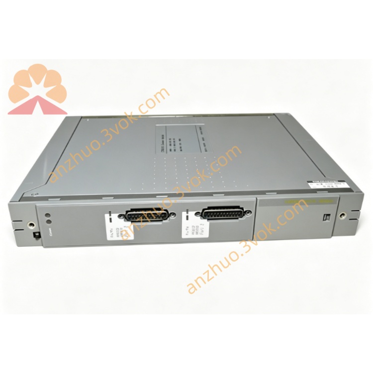
Terminals:
Input: TB1/TB2 (#8 screw terminals, redundant)
Output: TB3/TB4 (#6 screw terminals, redundant)
Status: J14/J15 (dry contacts for remote alarm)
Monitor: J13 (serial diagnostics)
3. Installation
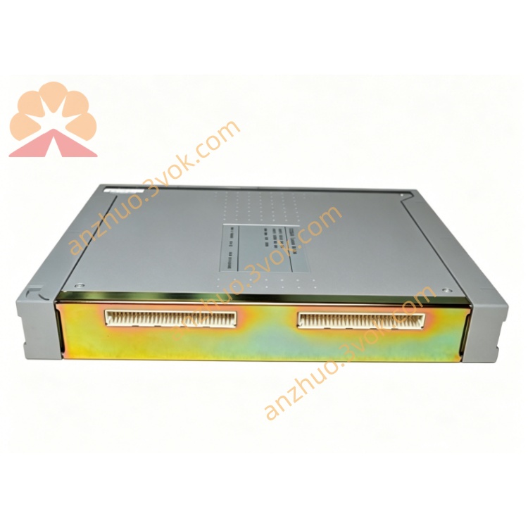
3.1 Chassis & Module Insertion (Hot‑Swap Enabled)
Install the Trusted power chassis (e.g., T8220 series) in a standard 19‑inch rack; secure mounting brackets.
Select an empty single‑width slot; remove the blank panel.
Align T8225 with chassis guides; push firmly until fully seated.
Secure the front latch to lock the module in place.
Repeat for additional modules (up to 3 per chassis for load sharing).
3.2 Wiring (Redundant Inputs/Outputs)
Input Power (TB1/TB2): Connect redundant AC or DC sources; use 14–18 AWG stranded wire; torque terminals to 1.2 N·m.
Output Power (TB3/TB4): Connect to system backplane and field I/O; use 12–16 AWG stranded wire; torque terminals to 1.5 N·m.
Status Contacts (J14/J15): Wire to remote alarm panel (fault = contact closed).
Grounding: Connect chassis PE to system earth; field ground isolated from chassis ground.
3.3 Redundancy & Load Sharing
Install 2–3 T8225 modules in the same chassis for active‑active current sharing.
System automatically balances load; single module failure triggers seamless switchover without downtime.
4. Front Panel Indicators
INPUT (Green): Steady = Normal; Flashing = Input fault (loss of one redundant source)
OUTPUT (Green): Steady = Normal; Flashing = Overvoltage/undervoltage
CURRENT (Yellow): Bar graph = Output current level (0–100 %)
FAULT (Red): On = Overcurrent/short‑circuit/overtemperature; Flashing = Internal fault
OK (Green): Steady = TMR vote healthy; Flashing = Single‑channel fault
5. Operation
5.1 Normal Operation
T8225 operates in redundant, current‑sharing mode; provides stable 24 V DC to system and field devices.
Diagnostics continuously monitor input/output voltage, current, temperature, and internal circuits; faults are logged to the system alarm list.
5.2 Fault Tolerance & Hot‑Swap
Single Input Fault: System runs on the remaining redundant input; INPUT LED flashes.
Single Module Fault: Remaining modules carry full load; FAULT LED on faulty module; OK LED flashes on healthy modules.
Hot‑Swap Replacement: Remove faulty module (unlatch, pull out); insert new module; system remains online during swap.
6. Maintenance & Troubleshooting
6.1 Routine Maintenance
Quarterly: Inspect seating, latch tightness, and LED status; check terminal torque.
Annually: Clean with dry, lint‑free cloth; verify grounding and cable integrity.
Diagnostics: Use Trusted Workbench or J13 monitor port to review fault logs and module status.
6.2 Common Faults
INPUT LED Flashing: Check redundant input sources; verify wiring and terminal torque.
OUTPUT LED Flashing: Measure output voltage; check for overloaded/short‑circuited field wiring.
FAULT LED On: Identify overcurrent/short‑circuit via diagnostics; disconnect field wiring and test; check for overtemperature (clean ventilation filters).
OK LED Flashing: Single internal channel fault; replace module at next scheduled maintenance.
7. Safety & Compliance
Install only in Trusted T8220 series power chassis; use in T8100/T8300 safety systems.
Disconnect all power sources before wiring (except hot‑swap module replacement).
Use shielded cables for field wiring to reduce EMI; comply with IEC 61000‑6‑2/4.
Compliant with: CE, UL, CSA, IEC 61508 (SIL 3), TÜV certified.
Get a Quote