ICS Triplex T820X Series Trusted Power Supply Module for SIL3 TMR Safety System
Description
TMR Architecture: Triple‑modular redundant power conversion; 2‑out‑of‑3 voting for fault tolerance.
Isolation: 2500 V pulse‑tolerant opto‑isolation between system and field sides.
Diagnostics: Full channel monitoring, overcurrent/short‑circuit protection, line fault detection.
Hot‑Swap: Modules can be replaced online without system shutdown.
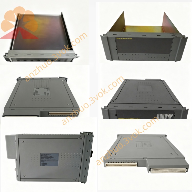
Form Factor: Single‑width (T8202) or double‑width (T8200/T8204) for Trusted chassis.
T8200: TMR I/O Power Supply Chassis (double‑width, main system PSU)
T8202: TMR I/O Power Supply Module (single‑width, 24 V DC, 40 channels)
T8204: Redundant I/O Power Supply (dual 24 V DC outputs, fault‑tolerant)
2. Specifications (General for T820X)
2.1 Electrical
Input Voltage: 20–32 V DC (backplane)
Output Voltage: 24 V DC ±5 % (isolated)
Output Current:
T8202: 40 channels × 0.5 A (max 20 A total)
T8200/T8204: 30–60 A total (per chassis)
Isolation: 2500 V DC (system ↔ field)
Protection: Overcurrent, short‑circuit, reverse polarity, overvoltage (auto‑reset)
Ripple: < 50 mV p‑p
Efficiency: > 85 % at full load
2.2 Environmental
Operating Temp: –20 °C to +60 °C
Storage Temp: –40 °C to +85 °C
Humidity: 5–95 % RH (non‑condensing)
Altitude: Up to 2000 m
Protection: IP40 (chassis mounted)
2.3 Mechanical
T8202 (Single‑Width): 160 × 80 × 120 mm; ~0.6 kg
T8200/T8204 (Double‑Width): 160 × 160 × 120 mm; ~1.2 kg
Mounting: Slides into T8100/T8300 chassis slot guides; front latch secured
Grounding: Chassis PE (protective earth) connected on insertion
3. Installation
3.1 Module Insertion (Hot‑Swap Enabled)
Verify target slot(s) in T8100/T8300 are empty (single/double width as required).
Remove blank panel(s) from the slot(s).
Align T820X with chassis guides; push firmly until fully seated.
Secure front latch to lock module in place.
Confirm PWR LEDs illuminate (steady green = healthy).
3.2 Field Wiring (24 V DC Outputs)
Terminals: Rear DIN41612 connectors (T8202: 40‑pin; T8200/T8204: 80‑pin)
Output Pairs: +24 V / GND (isolated per channel)
Cable: 18–22 AWG stranded, shielded (Belden 8760 or equivalent)
Termination: No external fuses required (per‑channel electronic protection)
Grounding: Field GND isolated from chassis PE; connect field shield to system earth at one point only.
3.3 Redundancy Setup (T8204)
Install two T8202 modules in adjacent slots (T8204 chassis).
Configure via Trusted Workbench for active‑active redundant operation.
System automatically balances load; single module failure triggers seamless switchover.
4. Configuration (via Trusted Workbench)
Connect PC with Trusted Workbench to the Trusted system.
Select T820X module in hardware tree.
Set global parameters:
Output Voltage: 24 V DC (fixed)
Overcurrent Threshold: 0.5 A per channel (default)
Fault Response: Latch off / auto‑reset (configurable)
Enable diagnostics:
Open‑circuit detection
Short‑circuit protection
Line voltage monitoring
Download configuration to the module.
5. Operation & LED Indicators
5.1 Front Panel LEDs (Common to All T820X)
PWR (Green): Steady = Normal; Flashing = Input power fault
OK (Green): Steady = TMR vote healthy; Flashing = Single‑channel fault
FAULT (Red): On = Overcurrent/short circuit; Flashing = Isolation fault
COM (Yellow): Flashing = Backplane communication active
5.2 Normal Operation
TMR power supplies operate in 2‑out‑of‑3 voting mode; single channel faults do not affect output.
Isolated 24 V DC power is distributed to I/O modules and field devices.
Diagnostics continuously monitor all channels; faults are logged to the system alarm list.
5.3 Fault Tolerance & Hot‑Swap
Single‑Channel Fault: System continues operating with two healthy channels; FAULT LED flashes.
Module Failure: Hot‑swap replacement allowed; system remains online during swap.
Redundant Configuration (T8204): Dual modules provide seamless failover; no downtime.
6. Maintenance & Troubleshooting
6.1 Routine Maintenance
Quarterly: Inspect seating, latch tightness, and LED status.
Annually: Clean with dry, lint‑free cloth; check cable connections and torque.
Diagnostics: Use Trusted Workbench to review fault logs and channel status.
6.2 Common Faults
PWR LED Off: Check backplane input voltage (20–32 V DC); reseat module.
FAULT LED On: Identify overloaded/short‑circuited channel via diagnostics; disconnect field wiring and test.
OK LED Flashing: Single TMR channel fault; replace module at next scheduled maintenance.
No Output Voltage: Verify field wiring and isolation barriers; check for blown internal fuses (rare).
7. Safety & Compliance
Install only in Trusted T8100/T8300 safety chassis.
Disconnect power before removal/installation (except hot‑swap).
Use shielded cables for field wiring to reduce EMI.
Compliant with: CE, UL, CSA, IEC 61508 (SIL 3), IEC 61000‑6‑2/4.
Get a Quote