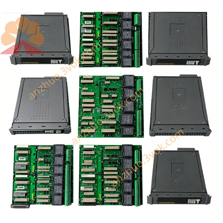
ICS Triplex T8094 Trusted General Signal Control Module for Industrial Safety Automation System
T8094 is a monolithic H‑bridge DC motor driver IC. It integrates power MOSFETs, control logic, and protection circuits into a single chip, enabling bidirectional drive, PWM speed control, and dynamic braking for small‑to‑medium brushed DC motors. It is widely used in consumer electronics, smart home devices, office equipment, and battery‑powered motor systems
Description
T8094 is a monolithic H‑bridge DC motor driver IC. It integrates power MOSFETs, control logic, and protection circuits into a single chip, enabling bidirectional drive, PWM speed control, and dynamic braking for small‑to‑medium brushed DC motors. It is widely used in consumer electronics, smart home devices, office equipment, and battery‑powered motor systems.
Features
Integrated H‑bridge structure supports bidirectional rotation and electric brake.Wide operating voltage range: 6V to 24V, compatible with 12V/24V motor systems.High output current capability: continuous up to 3A, peak up to 5A.Built‑in PWM generator for adjustable speed via duty cycle control.Logic inputs are CMOS/TTL compatible, allowing direct connection to MCU or logic circuits.Integrated over‑current, over‑temperature, and under‑voltage protection.Low on‑resistance minimizes power dissipation and heat generation.Available in compact SOP‑16 package for easy surface mounting.
Pin Definition
Pin 1 is ground reference.Pin 2 is motor output terminal A.Pin 3 is motor output terminal B.Pin 4 is power supply for internal logic.Pin 5 is H‑bridge power supply.Pin 6 is PWM speed control input.Pin 7 is forward direction control input.Pin 8 is reverse direction control input.Pin 9 is brake control input.Pin 10 is over‑current protection indicator.Pin 11 is thermal shutdown indicator.Pins 12 to 16 are reserved or no‑connect.
Working Logic
Forward operation: forward pin high, reverse pin low, brake pin low.Reverse operation: forward pin low, reverse pin high, brake pin low.Dynamic braking: brake pin high, direction pins arbitrary.Speed regulation: adjust PWM duty cycle on speed control pin.Protection state: output shuts down when over‑current or over‑temperature is detected.
Absolute Maximum Ratings
Maximum power supply voltage: 28V.Maximum output peak current: 5A.Operating temperature range: –25°C to +85°C.Storage temperature range: –55°C to +150°C.
Electrical Characteristics
Logic supply current typical: 8mA.On‑resistance per MOSFET typical: 80mΩ.PWM frequency range: 10kHz to 20kHz.Over‑current protection threshold typical: 4A.Thermal shutdown threshold typical: 170°C.
Application Circuit Description
Connect logic supply pin to 5V DC.Connect H‑bridge power supply pin to 6–24V DC.Connect ground pin to system ground.Connect motor terminals between output A and output B.Apply 0–5V PWM signal to speed control pin.Connect forward, reverse, and brake pins to MCU GPIO.Add 100nF decoupling capacitors near power pins.
Application Scope
DC motor drive for home appliances such as fans and pumps.Motor control for office equipment such as printers and scanners.Battery‑powered smart devices and portable tools.Industrial low‑voltage motor drive with speed and direction control.
Package Type
T8094 is packaged in SOP‑16, with dimensions 10.3mm × 7.5mm × 1.7mm.
Get a Quote