ICS Triplex T3464 Analog Input Module for SIL3 TMR Safety Instrumented SIS System
Description
2. Key Features
16 guarded AC outputs, grouped as two isolated banks of 8 channels each.
Fault‑tolerant parallel operation: Dual modules can work in parallel for uninterrupted load control.
Hot‑swappable: Online replacement without system shutdown.
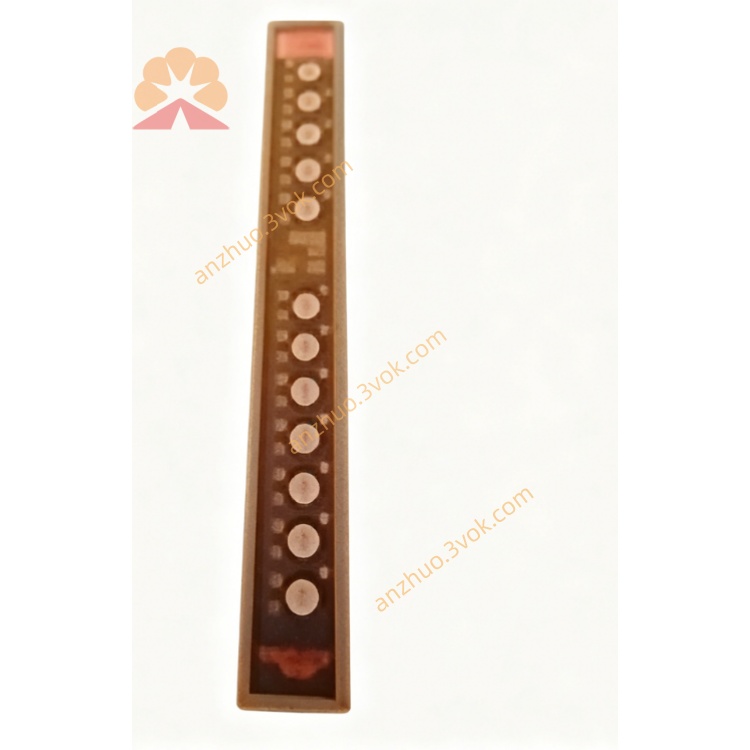
100% self‑diagnostics: Comprehensive fault detection with LED and display indicators.
Front‑panel accessible fuses: Simplifies maintenance.
2500 Vrms isolation: Between field and logic circuits for EMI protection.
TÜV certified (Risk Class 5): Compliant with IEC 61508 for safety integrity.
3. Technical Specifications
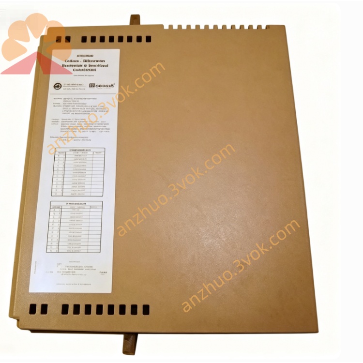
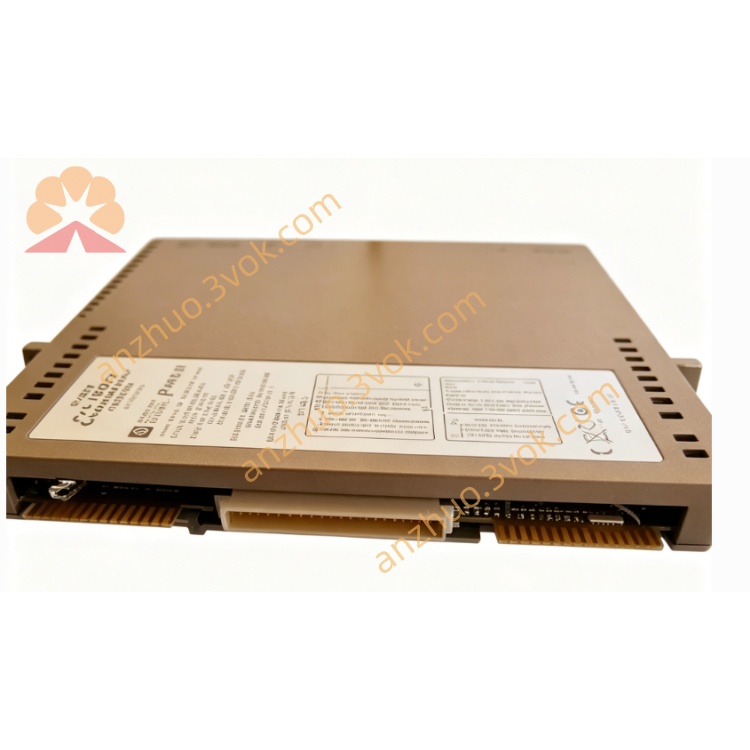
Model: T3464
Manufacturer: Rockwell ICS Triplex
System Compatibility: Regent/Trusted T3 series TMR systems
Input Voltage: 24 VDC ±10% (logic power)
Output Voltage: 110 VAC (user‑supplied field power)
Output Current: 4 A per channel; 32 A total
Isolation Voltage: 2500 Vrms (field‑to‑logic)
Power Consumption: 3 W (max)
Operating Temperature: −40°C to +70°C
Storage Temperature: −40°C to +85°C
Humidity: 5%–95% non‑condensing
Dimensions: 120 mm × 140 mm × 30 mm
Weight: 0.5 kg
Certifications: TÜV (Risk Class 5), CE, UL
4. Installation & Wiring
4.1 Mechanical Installation
Mount in a standard ICS Triplex T3 series rack (slots 0–15).
Ensure chassis grounding for ESD protection.
Maintain ≥25 mm clearance around the module for ventilation.
4.2 Wiring
Backplane Connector: Connects to system backplane for 24 VDC logic power and I/O Safetybus communication.
Field Terminals:
Two 110 VAC power inputs (for 8‑channel banks).
16 output channels (CH1–CH16) for field loads (valves, relays, contactors).
Cable Requirements: 16–20 AWG stranded copper wire; torque terminals to 0.8–1.0 N·m.
Fuses: Install 5 A fuses per bank (front‑panel accessible).
5. Operation
5.1 Power‑Up & Self‑Test
Apply 24 VDC logic power; the module runs a 5‑second initialization sequence:
Display test (8.8.8.8)
RAM/PROM self‑tests
Normal mode (blinking decimal points indicate processor activity)
“PWR” LED (green) lights; “FAULT” LED (red) remains off if healthy.
5.2 Normal Operation
Output Control: Triplicated commands from the system processor are voted by two independent microcontroller sections; outputs activate only if both sections agree.
LED Indicators:
Green: Channel ON.
Off: Channel OFF.
Red: Channel fault (overload/short circuit).
Display: Shows channel status and diagnostic codes (e.g., “AFO” for RAM failure).
5.3 Fault Handling
Channel Fault: Module disables the faulty channel; “FAULT” LED lights. Check wiring, load, or fuses.
Module Fault: Communication loss or internal error. Verify backplane connection or replace the module (hot‑swap supported).
6. Maintenance
Monthly Inspection: Check LED status, wiring tightness, and fuse condition.
Cleaning: Use a dry cloth to remove dust; avoid harsh chemicals.
Self‑Test: Trigger via system software quarterly to validate diagnostics.
Replacement: Hot‑swap procedure: remove faulty module, insert new one, and confirm operation via system diagnostics.
7. Safety Precautions
ESD Protection: Wear a grounded wrist strap when handling the module.
Power Isolation: Disconnect both 24 VDC logic power and 110 VAC field power before wiring.
Load Ratings: Do not exceed 4 A per channel or 32 A total current.
Fault Response: Address “FAULT” LED alerts immediately to maintain safety integrity.
Get a Quote