ICS Triplex T3441A TMR Safety Analog Output Module for SIL3 Safety Instrumented System
Description
2. Key Features
16 isolated output channels, 24 VDC rated.
Hot‑swappable design for online replacement without system shutdown.
TMR (Triple Modular Redundancy) architecture, SIL 3 certified (IEC 61508).
Overload/short‑circuit protection per channel.
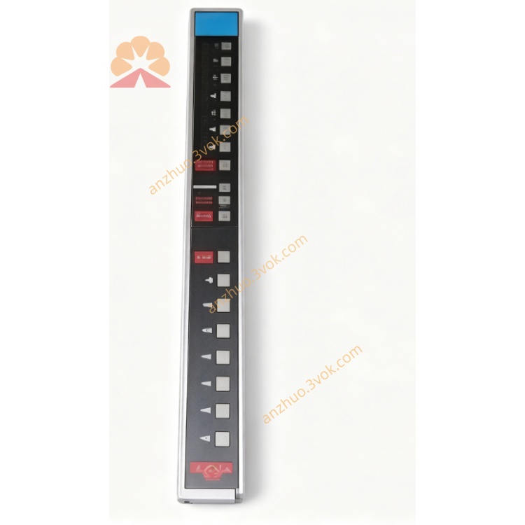
LED status indicators for power, fault, and individual channel state.
Wide operating temperature: −40°C to +70°C.
3. Technical Specifications
Model: T3441A
Manufacturer: Rockwell ICS Triplex
System Compatibility: Regent/Trusted T3 series control systems
Input Voltage: 24 VDC ±10%
Output Voltage: 24 VDC
Output Current: 2 A per channel; 32 A total
Isolation Voltage: 500 Vrms (channel‑to‑backplane)
Power Consumption: 2.5 W (max)
Operating Temperature: −40°C to +70°C
Storage Temperature: −40°C to +85°C
Humidity: 5%–95% non‑condensing
Shock: 30 g, 11 ms half‑sine
Vibration: 5 g, 10 Hz–500 Hz
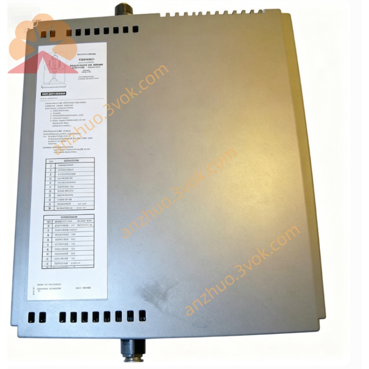
Dimensions: 120 mm × 123 mm × 63 mm
Weight: 0.5 kg
Certifications: SIL 3 (IEC 61508), CE, UL
4. Installation & Wiring
4.1 Mechanical Installation
Mount the module in a standard ICS Triplex T3 series rack (slot 0–15).
Ensure proper grounding of the rack and module chassis.
Allow ≥25 mm clearance around the module for ventilation.
4.2 Wiring
Backplane Connector: Connect to the system backplane for power and communication.
Field Terminals:
Positive (+24 VDC) and negative (GND) power for field devices.
16 output channels (CH1–CH16) for device control.
Cable Requirements: Use 18–22 AWG stranded copper wire; torque terminals to 0.8–1.0 N·m.
Isolation: Separate field wiring from control wiring to avoid EMI.
5. Operation
5.1 Power‑Up
Apply 24 VDC power to the rack; the “PWR” LED lights green.
The module performs self‑diagnostics; the “FAULT” LED turns red if a fault is detected.
5.2 Normal Operation
Channel Control: Outputs are switched ON/OFF via the control system logic.
LED Indicators:
Green: Channel ON.
Off: Channel OFF.
Red: Channel fault (overload/short circuit).
5.3 Fault Handling
Channel Fault: The module disables the faulty channel; the “FAULT” LED lights red. Replace the field device or check wiring.
Module Fault: Communication failure or internal error. Check backplane connection or replace the module.
6. Maintenance
Regular Inspection: Check LED status, wiring tightness, and module temperature monthly.
Cleaning: Keep the module free of dust; use a dry cloth.
Calibration: No periodic calibration required.
Replacement: Use hot‑swap procedure: remove the faulty module, insert a new one, and verify operation.
7. Safety Precautions
ESD Protection: Wear a grounded wrist strap when handling the module.
Power Off Before Wiring: Disconnect power before connecting/disconnecting field wiring.
Load Ratings: Do not exceed 2 A per channel or 32 A total current.
Environmental Limits: Operate within −40°C to +70°C; avoid condensation.
Get a Quote