DF9200847-B0N Product Technical Manual
Description
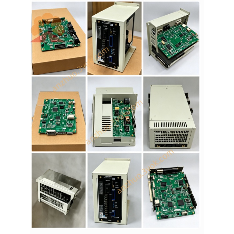
DF9200847-B0N Product Technical Manual
Manufacturer: Yaskawa
Model: DF9200847-B0N
Board Code: JANCD-SEN01
Product Type: Robot Controller, Safety Bus Communication Module
Compatible Systems: Motoman DX200, YRC1000 Robot Controllers
I. Product Overview
DF9200847-B0N is a dedicated module designed by Yaskawa for the safety-level network communication of robot workstations. It integrates safety Ethernet + standard industrial bus dual links, supporting safe protocol data interaction, safe I/O remote mapping, and safe interlock cross-site communication.
B0N is the safety-enhanced redundant version, meeting ISO 13849-1 PL d / IEC 61508 SIL2, used for multi-robot connection, production line safety interlock, and remote safe signal interaction. It is the core communication board card for building a safety networked workstation with DX200/YRC1000.
II. Physical Specifications
Board Form: Standard 6U VME industrial plug-in card
Dimensions: 233mm × 160mm × 20mm
Weight: Approximately 0.70kg
Interface Configuration
VME Backplane Bus Interface
CN1: Safety Ethernet RJ45 (Dual Redundant Ports)
CN2: Standard Industrial Ethernet RJ45
CN3: Safety Expansion Terminal (External Safety Circuit Connection)
Built-in Indicators:
PWR, RUN, SAFE, LINK1/LINK2, ACT, ALM, BUS
Process Characteristics
8-layer industrial PCB, gold-plated interface; whole board three-proof coating; safety partition isolation wiring; wide-temperature industrial components, anti-vibration, anti-EMC interference.
III. Versions and Compatibility
Version Spectrum
DF9200847-B0: Basic Safety Communication Version
DF9200847-B0N: Redundant Safety Enhanced Version (with dual links, fault redundancy)
Compatible Controllers
Fully compatible: DX200 Full Series, YRC1000
Incompatible: DX100, NX100 (Hardware Bus Architecture Different)
Replacement Relationship
B0N can directly replace B0, with downward functional compatibility
Common Ethernet Board (DF9200840) cannot be interchanged, without safety redundant protocol.
IV. Core Functional Characteristics
1. Safety Communication Capability
Supports safety Ethernet protocol, dual-link redundant transmission
Safe data interaction delay < 1ms
Safe signals cross-robot / cross-workstation real-time interlock
Meets PL d / SIL2 safety level, dual-channel verification, fault self-check
2. Industrial Bus Protocol Support
EtherNet/IP Safety Protocol
Modbus TCP Safety Mapping
Supports remote safe I/O mapping, read/write interlock signals
Maximum 512 points of safety input / 512 points of safety output can be mapped
3. System Function
Multi-machine group safety synchronous shutdown
Safe door, photoelectric, emergency stop network interlock
Safe fault log with timestamp storage, supports teach pendant / upper computer retrieval
Power-on automatic link detection, dual-link fault automatic switching, without interrupting safety logic
4. Isolation and Anti-interference
Safety network and ordinary network electrical isolation
Isolation withstand voltage 2500VAC
EMC industrial grade, compatible with welding, stamping strong electromagnetic environment
V. Electrical Parameters
Power Supply: VME Backplane 5VDC ± 5%
Overall Power Consumption: Approximately 13W
Operating Temperature: 0℃~+55℃
Storage Temperature: -20℃~+70℃
Humidity: 5%~90% RH without condensation ESD Protection: Air ±15kV, Contact ±8kV
VI. LED Status Definitions
PWR: Normal power supply, always on
RUN: Module operating normally, regular flashing
SAFE: Normal safety link, always on; Flashing = Abnormal safety link
LINK1/LINK2: Dual safety network interface link status
ACT: Data transmission and reception flashing
ALM: Hardware / Safety Fault Alarm
BUS: Fieldbus communication active
VII. Installation and Configuration Tips
Installation Location: VME expansion slot of DX200/YRC1000 controller
Cabling: Separate the safety network cable and power cable. Prioritize grounding of shielded network cable at one end.
Configuration: Enter the safety communication menu in the teaching device, set IP, safety link, interlock mapping
Replace with the same model B0N without jumper wires, automatically identified, only need to check the safety network parameters
VIII. Typical Applications
Integrated safety networking and interlocking for multi-robot workstations
Safety communication across workstations in automotive welding and assembly lines
Remote safety I/O expansion, networking of safety gratings / safety door groups
Automation production line networks requiring PL d / SIL2 certification
Get a Quote