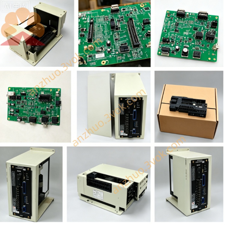
DF9200658-C0N (JANCD-MIF01N) Product Technical Manual
Description
DF9200658-C0N (JANCD-MIF01N) Product Technical Manual
Manufacturer: Yaskawa Electric Corporation
Product Model: DF9200658-C0N
Board Code: JANCD-MIF01N
Product Type: Robot Controller - Safety Enhanced Interface / Servo Communication Module
Applicable Systems: Yaskawa Motoman DX200, DX100, NX100 controllers (Specialized for high safety standard models)
I. Product Overview
DF9200658-C0N (JANCD-MIF01N) is a safety-enhanced version of the DF9200658-C0 developed by Yaskawa. As the core communication bridge between the controller CPU and servo, I/O, safety circuits, and teaching device, its core function is to meet the highest industrial safety level of ISO 13849-1 PL e and IEC 61508 SIL 3, specifically designed for high-risk automation scenarios such as automotive welding, stamping, and assembly lines. Compared to the C0 version, the N version has comprehensive upgrades in safety channels, redundant design, fault diagnosis, and anti-interference. The hardware and firmware are all of a safety-level dedicated architecture.
II. Physical Specifications
Board Form: Standard 6U VME industrial-grade PCB card (Safety Enhanced Structure)
Dimensions: Approximately 233mm × 160mm × 22mm (Slightly increased thickness, enhanced heat dissipation and shielding)
Weight: Approximately 0.65kg
Interface Configuration (Compatible with C0, independent safety channel enhancement)
VME System Bus (CPU Communication)
CN1: SSCNET III Servo Fiber Optic Interface (8 Axes)
CN2: Encoder Feedback (Differential RS-422)
CN3: Teaching Device Interface
CN4: Safety-specific I/O (Dual Redundant Channels) (Emergency Stop, STO, Safety Door, Safety Scanner)
CN5: General I/O Expansion (24VDC)
CN6: System Power Supply (5V + 24V Dual Independent)
LED: PWR/RUN/ALM/COM/SV/SAFE1/SAFE2 (Dual Safety Status Lights)
Structural Process
10-layer PCB, strict control of differential impedance, gold plating and thickening
Full board three-coat coating + EMI shielding cover (Independent shielding in safety area)
Wide Temperature Range: -20°C to +60°C (Industrial Enhancement)
Gold-plated Interfaces: Insertion and Ejection Life ≥ 1500 Times
Shaking / Impact Resistance: Reinforced, suitable for intense vibration environments in production lines
III. System Compatibility
Applicable Controllers
Motoman DX200 (Main Configuration, Safety Firmware Ver.7.5+)
Motoman DX100 (Safety Extended Model)
Motoman NX100 (High Safety Configuration)
Compatible Servos
Yaskawa Σ-7, Σ-X Series (Native Support for Safety STO)
Compatible Σ-5 (Requires Safety Adapter Board)
Version Spectrum
Basic Version: DF9200658-B0 (JANCD-MIF01)
Standard Version: DF9200658-C0 (JANCD-MIF01B)
Safety Enhanced Version: DF9200658-C0N (JANCD-MIF01N) - Highest Safety Level
IV. Core Functional Characteristics (Safety Enhancement Focus of N Version)
1. Safety Function (PLe/SIL3 Level, Core Difference)
Dual Redundant Safety Channels: Safety I/O, STO, Emergency Stop are all dual-channel independent circuits, single-point failure does not affect safety Safe Torque Off (STO): PLe / SIL 3, response time **< 0.5ms** (C0 is PLd/SIL2, < 1ms)
**Safety Stop (SS1/SS2), Safety Speed Limit (SLS), Safety Position (SOP)** hardware support
Emergency Stop: Dual-channel hardwired redundancy + cross-check, real-time diagnosis for disconnection / short circuit
Safety I/O: 16 points of safety-specific (8 input / 8 output), 24VDC, 1500VAC isolation, PLe certification
Hardware latch for safety status + non-volatile storage, must be manually reset after failure + password unlock
2. Servo Bus Control
SSCNET III: 1Gbps optical fiber, 8-axis synchronization, safety message extension
Servo Safety Feedback: Double encoder verification, position / speed safety monitoring
Safety Faults: Bus-level emergency cut-off, < 0.2ms to cut off servo commands
Support for dual-machine safety collaboration, external axis safety linkage
3. Communication and I/O
VME Bus: 16Mbps, safety CRC verification
Teaching Device: Differential transmission, safety enable dual channels, immediate shutdown in case of disconnection
General I/O: 48 points (24 input / 24 output), 24VDC, photoelectric isolation, physical isolation between safety zone and non-safety zone
I/O Response: < 0.5ms, interrupt / high-speed position comparison compatibility
4. Protection and Diagnosis (Safety Level)
Overvoltage / undervoltage / overcurrent / short circuit: Dual-channel hardware protection + redundant monitoring
Safety Faults: 32-bit precise code + dual-channel independent diagnosis
LED + Controller + Safety Log Triple-state Display
Watchdog: Dual watchdog interlock, immediate cut-off of safety output in case of abnormality
EMC/ESD: ±25kV air, ±12kV contact (far exceeding C0 version)
5. Electrical Parameters Power supply
Main power supply: 5VDC ±5%, 2.5A (with safety filtering enhancement)
Servo interface: 24VDC ±10%, 1.5A
Safety circuit: 24VDC ±10%, 0.8A (dual independent paths)
Isolation withstand voltage: 3000VAC (safety channel) Signal
SSCNET III: Fiber optic 1Gbps, Security Protocol Expansion
Security I/O: 24VDC, PLe/SIL3
General I/O: 24VDC, Source/Sink Universal
Encoder: 5V Differential RS-422, Dual Checksum Performance
Security Response: <0.5ms
Control Cycle: 0.5–8ms (0.5ms in Safe Mode)
MTBF: >100,000 hours (40°C)
Position Accuracy: ±0.5 pulses (Safety Monitoring)
VI. Key Upgrades of C0N vs C0 (Clear at a Glance)
Security Level: C0N = PLe/SIL3; C0 = PLd/SIL2
Safety channels: C0N = Dual redundant independent circuits; C0 = Single channel
Safety functions: C0N = STO + SS1 + SS2 + SLS + SOP; C0 = STO base
Response time: C0N = < 0.5ms; C0 = <1ms
Isolation withstand voltage: C0N = 3000VAC; C0 = 1500VAC
ESD protection: C0N = ±25kV/±12kV; C0 = ±15kV/±8kV
Safety I/O: C0N = 16 dedicated; C0 = integrated multiplexing
Firmware: C0N = security encryption + signature authentication; C0 = standard firmware
Application scenarios: C0N = automotive / stamping / high-risk; C0 = general automation
VII. LED Status Indicators
PWR (green): 5V normal
RUN (green): operation (1Hz)
ALM (red): fault (constant on = hardware, flashing = safety fault)
COM (yellow): VME communication
SV (yellow): servo bus
SAFE1 (green): safety channel 1 normal
SAFE2 (green): safety channel 2 normal (double safety lights)
VIII. Installation and Maintenance
Slot: VME 1 slot (safety priority)
Grounding: <0.5Ω (dual-ended independent grounding)
Cabling: strict separation and shielding of safety cables, optical fibers, and power lines
Tightening: 0.22–0.25N・m
Maintenance: annual full-function safety circuit test; regular cleaning of optical fibers; firmware only official safety version
IX. Safety Fault Diagnosis (Typical)
SAFE1/SAFE2 extinguished: dual-channel safety fault (emergency stop, STO, safety door, wiring)
ALM + SAFE flashing: safety check error (dual paths inconsistent)
Servo without safety response: SSCNET safety message anomaly
Safety output not connected: hardware latch / reset failure / password not unlocked
X. Safety Certification ISO 13849‑1 PLe
IEC 61508 SIL 3
UL 508, CE (LVD/EMC), RoHS, IEC 61010
Document Description: This manual is compiled based on the official parts specifications of ABB, the DX200 safety controller manual, and the C0N hardware safety standards. It is specifically designed for high-security level spare parts selection, debugging, acceptance, and maintenance.
Get a Quote