DF9200471-D1 (JANCD-MTV01 Rev. D13) Technical Manual
Description
DF9200471-D1 (JANCD-MTV01 Rev. D13) Technical Manual
1. General Description
2. Physical Specifications
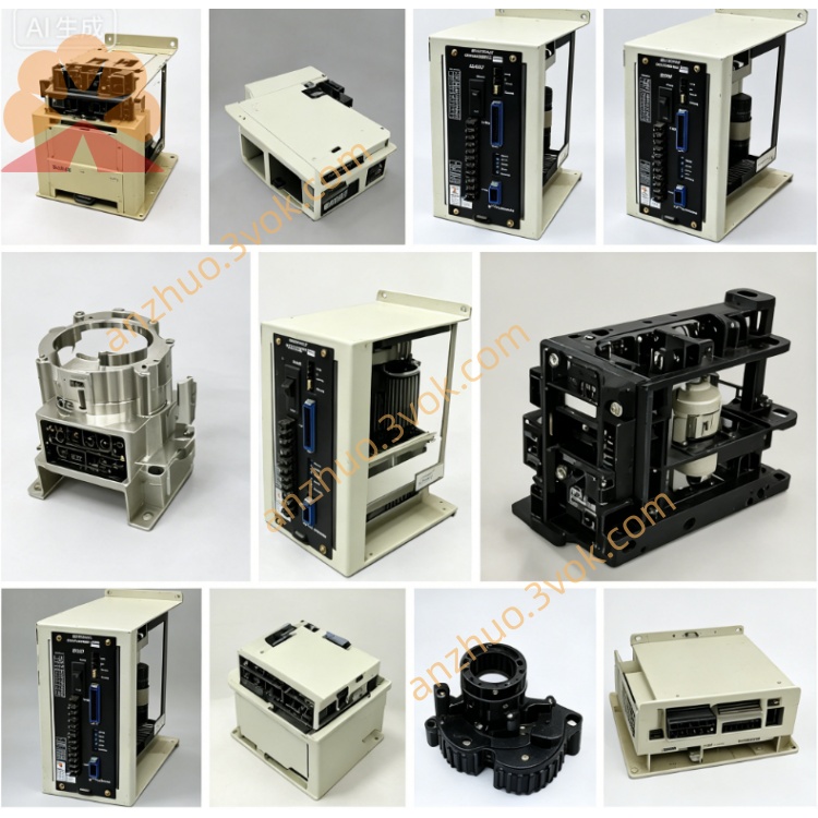
Form Factor: Industrial PCB Module (Standard 6U VME-compatible rack mounting)
Dimensions: Approx. 160mm (H) x 233mm (W) (Standard VME footprint)
Weight: Approximately 0.60 KGS (600g)
Connectors:
Multiple high-density terminal blocks for power input/output
Multi-pin industrial connectors for servo power distribution
Edge-type connector for system bus interface
Screw terminals for auxiliary power and grounding
Construction:
Multi-layer industrial-grade PCB with heavy copper power planes
Through-hole and surface-mount component assembly
Conformal coating for environmental protection
Integrated heat dissipation paths for power regulation circuits
Mounting: Vertical rack mounting in Yaskawa Motoman controller cabinets
3. Compatibility
Primary Controller Systems:
Motoman MRC (Multi-Robot Controller) Series
Motoman XRC (Extended Robot Controller) Series
Robot Series Compatibility:
Motoman UP Series (e.g., UP6, UP20, UP50)
Motoman HP Series (e.g., HP6, HP20, HP50)
Motoman MS Series
Motoman SK Series
Related / Companion Modules:
JANCD-MTU01 (Related power/control board variant)
JANCD-SV02 Series (Servo CPU control boards)
DF9200414 Series (Servo axis control modules)
4. Functional Features
Multi-Channel Power Distribution:
Regulates and distributes primary servo system power
Provides isolated power for logic and I/O circuits
Manages power delivery for up to 8+ servo axes
Voltage Regulation & Stabilization:
Precision voltage regulation for critical servo circuits
Active noise filtering and ripple suppression
Over-voltage / under-voltage monitoring and protection
Over-Current & Short-Circuit Protection:
Integrated electronic fusing for each power channel
Over-current detection and automatic shutdown
Short-circuit protection with fault indication
System Monitoring & Diagnostics:
Real-time voltage and current monitoring
Power supply status LED indicators
Fault condition detection and reporting to main CPU
Isolation & Safety:
Galvanic isolation between input and output circuits
Optical isolation for control signals
Compliance with industrial safety standards for power control
5. Electrical Specifications
Input Power Requirements:
Primary Input: 200-240 VAC, 50/60 Hz (Main controller supply)
Logic Input: 24 VDC ±10% (Auxiliary control power)
Output Power Channels:
Servo Drive Power: 200-240 VAC (Distributed to axis amplifiers)
Logic Power: 5 VDC ±5%, 10A (For servo CPU and logic circuits)
I/O Power: 24 VDC ±10%, 5A (For peripheral I/O and sensors)
Auxiliary Power: ±15 VDC (For analog and feedback circuits)
Power Efficiency: Typical 85% efficiency at full load
Ripple & Noise: < 1% peak-to-peak (Output voltage ripple)
Isolation Voltage: 2500 VAC (Input to output isolation)
In-Rush Current Limiting: Integrated soft-start circuitry
6. Operating Environment
Operating Temperature: 0°C to +45°C (Industrial standard)
Storage Temperature: -20°C to +70°C
Humidity: 10% to 90% RH (Non-condensing)
Vibration Resistance: 10-60Hz, 0.5G maximum (Compliant with IEC 60068-2-6)
Shock Resistance: 10G (11ms duration, half-sine wave)
Pollution Degree: 2 (Industrial environment)
Altitude: Up to 1000m above sea level
7. Revision Information
DF9200471-D1: Primary model designation
JANCD-MTV01 Rev. D13: Full board revision (Current latest)
Enhanced over-current protection thresholds
Improved thermal design for higher power loads
Updated component selection for extended MTBF
Compatibility with newer MRC/XRC controller firmware
Previous Revisions: Rev. D, Rev. D10, Rev. D11, Rev. D12
8. Maintenance & Service
MTBF (Mean Time Between Failures): > 80,000 hours at 40°C
Service Life: 15+ years under proper operating conditions
Component Life: Electrolytic capacitors rated for 10 years at 40°C
ESD Sensitivity: Class 1 (ESD protection required during handling)
Warranty: Standard 12 months (365 days) for new/reconditioned units
Repairability: Professional component-level repair services available
Firmware: No programmable firmware (Hardware-based power control)
9. Installation Guidelines
Mounting: Secure vertical mounting in dedicated controller rack slot
Grounding: Dual-point connection to cabinet earth ground (Low impedance < 1Ω)
Cabling:
Use shielded power cables for all high-current connections
Separate power cables from low-voltage signal cables
Ensure proper strain relief for all connectors
Torque Specifications:
Power terminal screws: 1.2 – 1.5 N·m
Signal connectors: 0.22 – 0.25 N·m
Pre-Startup Checks:
Verify all voltage settings match system requirements
Check for secure connections and proper insulation
Perform initial power-on test with no load connected
10. Troubleshooting & Fault Indications
PWR1 (Green): 5V logic power OK
PWR2 (Green): 24V I/O power OK
FAULT (Red): Over-current / over-voltage / short-circuit detected
OVLD (Amber): Overload condition (Excessive current draw)
Voltage Drop: Indicates insufficient input power or excessive load
Over-Current Fault: Short-circuit on output channel or faulty servo drive
Over-Temperature: Poor ventilation or component failure
Isolation Fault: Ground loop or insulation breakdown
Record all LED statuses at fault occurrence
Disconnect all output loads and retest (Isolate faulty channel)
Verify input voltage levels are within specification
Check for loose connections or damaged cables
Replace unit if fault persists with no loads connected
11. Part Number Cross-Reference
DF9200471-D1: Primary Yaskawa part number
JANCD-MTV01 Rev. D13: Full board assembly number
RP1016-545A-16-10: Alternative manufacturer part number
JANCD-MTU01: Similar function board variant
DF9200471-D: Base model without revision suffix
12. Safety & Compliance
Standards Compliance:
IEC 61010 (Safety requirements for electrical equipment)
UL 508 (Industrial control equipment)
CE (Low Voltage Directive 2014/35/EU)
Safety Features:
Non-fused power disconnect capability
Emergency stop circuit integration
Lockout / Tagout compatible design
Handling Precautions:
Always disconnect power before installation/removal
Use ESD wrist strap and mat during handling
Do not operate outside specified environmental limits
Get a Quote