YASKAWA USAJKM-30-MN22 AC SERVO MOTOR SPECIFICATION
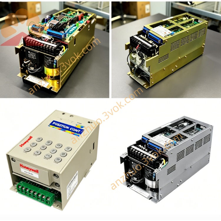
USAJKM-30-MN22 belongs to Yaskawa classic USAJKM medium-inertia AC servo lineup under M-series platform, specially customized for European industrial market with MN customized encoder wiring standard and dual independent rear round connectors marked by suffix code MN22. This unit adopts fully enclosed fan-cooled structure with auxiliary external cooling fan design to sustain stable continuous output under long-duration heavy-load running conditions, equipped with factory-built electromagnetic power-off brake inside motor housing and standard keyed solid output shaft layout. Optimized for frequent cyclic acceleration-deceleration and large inertia load driving scenarios, the servo is developed to pair with original CACR series EU-version servo amplifiers and early-generation SGDM servo drives, widely used on medium-load automation equipment requiring reliable shaft holding when power supply cuts off unexpectedly. Low cogging torque and optimized rotor inertia design deliver consistent positioning repeatability for precision indexing and feeding motion in automated production lines.
Description
YASKAWA USAJKM-30-MN22 AC SERVO MOTOR SPECIFICATION
1. Product Introduction
USAJKM-30-MN22 belongs to Yaskawa classic USAJKM medium-inertia AC servo lineup under M-series platform, specially customized for European industrial market with MN customized encoder wiring standard and dual independent rear round connectors marked by suffix code MN22. This unit adopts fully enclosed fan-cooled structure with auxiliary external cooling fan design to sustain stable continuous output under long-duration heavy-load running conditions, equipped with factory-built electromagnetic power-off brake inside motor housing and standard keyed solid output shaft layout. Optimized for frequent cyclic acceleration-deceleration and large inertia load driving scenarios, the servo is developed to pair with original CACR series EU-version servo amplifiers and early-generation SGDM servo drives, widely used on medium-load automation equipment requiring reliable shaft holding when power supply cuts off unexpectedly. Low cogging torque and optimized rotor inertia design deliver consistent positioning repeatability for precision indexing and feeding motion in automated production lines.
Model Code Explanation
USAJKM stands for fan-cooled medium-inertia rare-earth magnet servo base series; numeral 30 defines rated power grade at 3.0kW standard rating; MN refers to European exclusive pin definition for differential incremental encoder and internal brake configuration; digit 22 indicates dual separate circular rear connectors for power cable and encoder signal harness respectively.
2. Electrical Technical Parameters
The servo motor is rated for three-phase AC 200V~230V industrial power input compatible with 50Hz and 60Hz mains frequency. Its nominal continuous rated output power is 3.0kW with rated working speed fixed at 3000rpm and permissible short-time maximum no-load speed up to 4000rpm. Continuous rated output torque reaches 9.55Nm while instantaneous peak overload torque can achieve three times of rated torque to handle startup heavy inertia shock and transient impact load during jog operation. Nominal full-load continuous input current is 15.2A under standard rated operating condition; internal stator winding uses Class F insulation grade with embedded temperature detection element feeding overheat protection signal to matched servo drive for automatic cutoff against over-temperature burnout from prolonged overloading.Built-in DC24V electromagnetic brake coil is pre-installed inside motor body, requiring external 24VDC power supply input to release brake lock for normal shaft rotation; brake generates fixed static holding torque to lock output shaft reliably once input power fails, preventing free falling of vertically mounted mechanical structure. The fitted differential line-drive incremental encoder follows exclusive MN custom pinout conforming to EU wiring standard with fixed pulse resolution, transmitting anti-interference position feedback signal to realize three closed-loop control modes including position, speed and torque via matched original servo amplifier. All internal circuit sections are fitted with surge suppression components to suppress site industrial power surge and electromagnetic interference from adjacent inverter equipment.
3. Mechanical & Environmental Specifications
Overall motor housing complies with IP54 protection grade against workshop floating dust and incidental water splashing; external forced air cooling by built-in auxiliary fan enhances heat dissipation efficiency for continuous high-load operation compared with natural cooling models. Output shaft is standard straight solid shaft with integrated flat keyway for direct coupling connection with ball screw, precision planetary reducer or timing belt wheel without extra adapter modification, and total net weight of complete motor assembly is approximately 7.8kg with standard flange mounting dimension for fixed equipment installation.Permitted working ambient temperature ranges from 0°C to +40°C, while storage environmental temperature spans from -20°C up to +70°C during spare part stocking period; applicable relative working humidity keeps between 5%RH and 80%RH under non-condensation status to avoid internal winding short circuit caused by dew condensation. When installation altitude exceeds 1000 meters above sea level, users need to derate continuous output power moderately due to declined cooling performance of forced air cooling structure under thin air condition. The unit withstands standard industrial vibration test within 10Hz~55Hz frequency range; long-term service in environment filled with corrosive gas, conductive dust or continuous liquid splash is prohibited to extend service life of bearing, brake friction plate and internal winding. Factory delivery withstand voltage test is 1500VAC applied for one minute between winding and motor shell, and insulation resistance tested under 500VDC maintains over 10 megaohm after outgoing inspection. MN22 dual-connector design separates power circuit and encoder signal wiring independently to minimize cross interference under long-term equipment vibration working environment.
4. Matching Drive & Control Description
Original matched servo controller is Yaskawa European specification CACR high-power series servo pack or early SGDM type servo drive unit with corresponding regional firmware parameter setting. The complete servo system supports two mainstream external command input types: ±10VDC analog voltage speed instruction and differential pulse position command sent from upper CNC system or industrial PLC controller, enabling flexible mode switching among position closed loop, speed closed loop and torque closed loop according to different production technological requirements. Built-in automatic gain tuning algorithm inside matched drive optimizes servo parameters automatically after initial power-on commissioning to shorten mechanical debugging cycle and improve overall dynamic response of transmission mechanism. Full mechanical origin homing operation must be executed after complete power outage to restore accurate zero point position before formal equipment production start.
5. Protection Function & Maintenance Guidance
Cooperating with matched servo amplifier, multi-level comprehensive fault protection system is configured, including winding overheat shutdown protection triggered by built-in temperature sensor, encoder wire break or poor contact alarm, main circuit overcurrent and winding short-circuit instantaneous power-off protection, as well as brake abnormal power supply fault alarm function. Before any disassembly maintenance for bearing replacement, encoder calibration or brake friction plate inspection work, operators must fully cut off three-phase main input power and wait minimum 15 minutes for full discharge of DC bus residual electricity inside servo drive to eliminate high-voltage electric shock risk.Routine periodic maintenance items include regular tightening inspection of dual rear connector terminals every three months, supplementary filling of high-temperature resistant bearing grease after accumulating 8000 continuous working hours, periodic cleaning of cooling fan and casing dust every half year to guarantee rated heat dissipation effect, and regular check of brake friction plate abrasion condition every six months for vertical installation application. Arbitrary alteration to original MN-defined encoder pin assignment or internal brake wiring will easily cause out-of-control motor runaway and permanent drive fault locking.
6. Typical Application Scope
This medium-inertia brake-equipped servo motor is widely applied on medium-load automatic packaging machinery, large-format desktop CNC feed axis system, automatic stamping and indexing equipment, SMT large-scale board conveying positioning equipment, vertical installation automated lifting mechanism and non-standard customized medium-duty automation equipment that demands reliable power-off shaft holding and high-precision repeated positioning under continuous heavy cyclic load operating conditions.
Get a Quote