1. Product Introduction
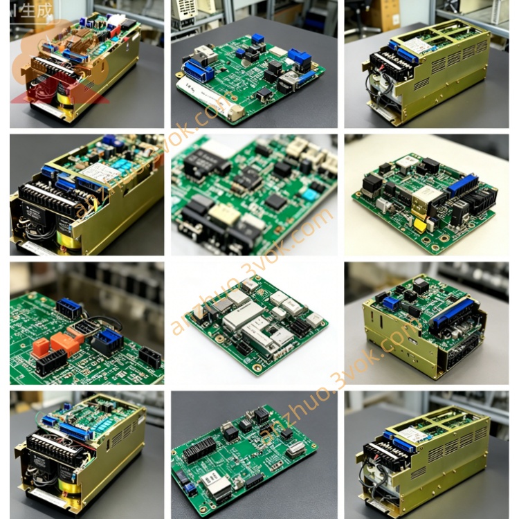
CACR-SRCA30BBSY124 is a customized OEM locked 3.0kW 200V-class digital AC servo amplifier under Yaskawa VS800 CNC servo series, upgraded SRCA special control mainboard version different from standard SR base hardware, suffix Y124 stands for exclusive factory pre-burned customized locked firmware for designated OEM CNC machine tools. Compared with general non-Y suffix CACR-SRCA30BBS standard drive, core control parameters, I/O definition and control logic are write-protected permanently by factory program; end user cannot modify key tuning parameters freely, only match specified original incremental encoder servo motor and supporting CNC host system. It retains dual command input hardware design: ±10V analog speed instruction plus differential pulse position command for CNC feed axis positioning control.
Model Code Definition
CACR: VS800 CNC dedicated feed servo series designation
SRCA: Enhanced control mainboard specification with expanded I/O and internal logic circuit vs ordinary SR model
30: Rated matched motor power = 3.0kW
BB: Customized PCB hardware layout exclusive for SRCA platform
S: Separated independent power supply for main power loop and control circuit
Y124: Exclusive OEM fixed locked customized firmware code, fixed parameter & I/O solidified by machine maker requirement
2. Main Electrical Specifications
Power Supply Rating
Main circuit input: 3-phase AC200V~230V, 50/60Hz, permissible voltage deviation +10%/-15% of nominal input voltage. Control circuit uses independent single-phase AC200V~230V isolated power source to avoid power fluctuation interference from main power load change; nominal DC bus rectified voltage ranges DC280V~320V.
Output Performance
Continuous rated RMS output current matches 3.0kW power grade; overload capability: 150% rated current sustainable for 60s continuous running, peak 300% overload within 3s for rapid acceleration startup. Adopts IGBT sine-wave PWM driving topology, maximum output frequency 300Hz for three-phase variable AC output toward matched servo motor. Terminals P-BN are reserved for external regenerative braking resistor wiring to consume regenerative energy during frequent deceleration and emergency stop operation.
Interface Configuration
R/S/T: Three-phase main AC power input terminals; U/V/W: Three-phase motor power output terminals; P/BN: External brake resistor connection terminals.
CN1: Optocoupler isolated digital I/O connector, all pin signal functions pre-fixed by Y124 customized firmware without user redefinition permission.
CN2: Encoder feedback port limited exclusively to OEM-specified incremental encoder; absolute encoder function is disabled by locked program as factory setting. Front LED seven-segment display shows running status and standard VS800 fault codes.
3. Unique Customized Y124 Firmware Features
Core parameter write lock: Position loop gain, speed PI proportional/integral parameters, S-type acceleration/deceleration coefficient and filter parameters are pre-set and write-protected; users only realize parameter reading without modification access via panel or serial communication.
Fixed single control mode: Firmware solidified to position control mode by default; switching between speed/torque/position control via parameter setup is completely forbidden.
Fixed CN1 I/O allocation: All input/output signal logic is locked inside program, no free I/O mapping adjustment available.
RS422 serial communication restriction: Serial port only supports real-time data reading and fault history query; all parameter write/download operations are blocked by OEM program lock.
Fixed electronic gear ratio value: Electronic gear setting is pre-calibrated at factory to match machine mechanical structure, parameter modification prohibited entirely.
4. Environmental & Installation Specifications
Operating ambient temperature: 0℃ ~ +55℃; storage temperature: -20℃ ~ +70℃. Operating relative humidity 5%~80%RH without internal condensation. Derate continuous output load when installation altitude over 1000m above sea level. Product protection grade IP20, only vertical cabinet installation allowed; minimum 50mm upper and bottom clearance reserved inside cabinet for radiator heat dissipation.
Safety operation rule: Cut off all AC input power and wait minimum 15 minutes for internal DC bus capacitor full discharge before plug/unplug CN1/CN2 connectors; powered hot plug is strictly prohibited. Unit net weight approx 1.3kg per original factory specification.
5. Built-in Full Protection Functions
Integrated standard VS800 multi-protection system including output overcurrent protection, DC bus overvoltage/undervoltage shutdown, power module overheat protection, encoder wire break detection, long-time motor continuous overload protection and main CPU abnormal fault alarm. Latest 10 groups of fault data stored inside nonvolatile memory, fault records reserved after power failure or manual reset. Small built-in dynamic brake resistor handles regular light-load stop; external braking resistor must be installed on P-BN terminals under heavy-duty and frequent emergency stop application condition.
6. Replacement & Application Instruction
Application Scope
Exclusively customized for specific brand CNC lathe, vertical small machining center feed axis motion control; only original matching complete machine supporting spare part, cannot be directly applied on ordinary non-customized general automation equipment.
Replacement Regulation
Hardware dimension and electrical interface fully compatible with standard CACR-SRCA30BBS non-custom model, yet standard general drive cannot direct plug-and-play replacement due to unmatched Y124 locked firmware and fixed parameter setting. Only identical part CACR-SRCA30BBSY124 realizes seamless replacement; if using non-Y124 standard unit for substitution, professional factory must rewrite exclusive Y124 customized firmware before field commissioning.
Prohibit full parameter factory reset on Y124 version; reset operation will erase pre-locked OEM parameters and cause motor runaway or complete machine abnormal alarm.
7. Standard VS800 Series Fault Code Definition
1 = Output overcurrent fault
3 = DC bus overvoltage protection triggered
4 = DC bus undervoltage alarm
5 = Internal power module overheat shutdown
6 = Encoder cable disconnection error
7 = Long-term continuous motor overload protection
A = Main control CPU abnormal failure
C = External emergency stop signal input activated
Get a Quote