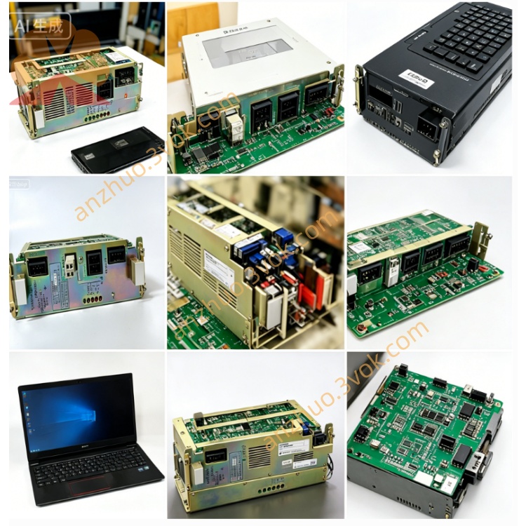
CACR-SR30SB1BSY119
CACR-SR30SB1BSY119 is an OEM factory-locked customized full-digital AC Servopack belonging to YASKAWA YASNAC VS800 servo series, rated for 3.0kW 200V-grade dedicated CNC machine tools and special automated production equipment. The suffix Y119 represents exclusive solidified customized OEM firmware preset at factory side; core control gains, I/O pin allocation and running control logic are write-protected, which cannot be arbitrarily modified by end users compared with non-Y-suffix standard universal model CACR-SR30SB1BS. This servo supports dual command input including ±10VDC analog speed signal and differential pulse position instruction, and only matches the designated incremental encoder servo motor specified by Y119 customized program.
Description
1. Product Overview
CACR-SR30SB1BSY119 is an OEM factory-locked customized full-digital AC Servopack belonging to YASKAWA YASNAC VS800 servo series, rated for 3.0kW 200V-grade dedicated CNC machine tools and special automated production equipment. The suffix Y119 represents exclusive solidified customized OEM firmware preset at factory side; core control gains, I/O pin allocation and running control logic are write-protected, which cannot be arbitrarily modified by end users compared with non-Y-suffix standard universal model CACR-SR30SB1BS. This servo supports dual command input including ±10VDC analog speed signal and differential pulse position instruction, and only matches the designated incremental encoder servo motor specified by Y119 customized program.
Model Code Definition
CACR stands for VS800 dedicated feed-axis servo series for CNC machine tool drive; SR refers to dual command input hardware design compatible with analog speed and differential pulse position signals; numeral 30 corresponds to rated 3.0kW matching servo motor capacity; SB is customized specification main control PCB layout different from standard BE board; digit 1 stands for separated independent power supply configuration for main circuit and control circuit; BS is basic base firmware platform; Y119 is exclusive OEM locked customized firmware code with fixed machine-tailored parameters and fixed I/O definition. Standard non-Y119 general version cannot achieve direct plug-and-play replacement unless authorized manufacturer rewrites dedicated Y119 firmware onto alternative hardware.
2. Electrical Specifications
Main circuit input is three-phase AC200V~230V applicable for 50Hz and 60Hz industrial power grids, allowable input voltage fluctuation ranges from minus fifteen percent to plus ten percent of rated voltage. Control power is fed via independent single-phase AC200V~230V to isolate voltage disturbance generated from main circuit load variation.
Continuous rated RMS output current matches 3.0kW specification accordingly; overload performance is defined as 150% rated current sustainable for continuous 60-second operation and 300% peak overload limited within 3 seconds during motor startup acceleration phase. The driver adopts IGBT sine-wave PWM modulation with maximum output frequency up to 300Hz, nominal DC bus operating voltage falls between DC280V and DC320V. Terminals P and BN are reserved for external regenerative braking resistor connection to consume regenerative feedback energy under frequent deceleration and emergency stop working conditions. Protection grade is IP20 and only vertical cabinet installation is permitted, unit net weight is heavier than 1.5kW specification in accordance with 3.0kW power grade. CN2 feedback port is fixed for Y119-specified incremental encoder only; original customized firmware disables access for absolute encoder and backup battery wiring function.
Exclusive customized features of Y119 version: position loop gain, speed loop PI parameters, acceleration and deceleration settings as well as filter coefficients are pre-set and locked inside customized firmware without user modification permission. Default control mode is fixed by factory programming and free switching among speed, position and torque control modes is prohibited. RS422 serial communication only supports reading real-time running data and historical fault logs; parameter upload, download and modification functions are fully blocked by program restriction.
3. Environmental and Installation Specifications
Operating ambient temperature ranges from 0°C to +55°C, storage temperature covers -20°C to +70°C. Working relative humidity keeps between 5% and 80% without internal condensation on electronic components inside casing. Reduce continuous output load appropriately when installation altitude exceeds 1000 meters above sea level to avoid unexpected overheat protection triggering.
Applicable working vibration condition is 10Hz~55Hz with single vibration amplitude limited to 0.5mm. Reserve more than 50mm ventilation clearance on top and bottom inside control cabinet to guarantee sufficient heat dissipation airflow. Cut off all AC power supply and wait no less than 15 minutes for complete discharge of internal DC bus capacitor before opening casing or plugging CN1 and CN2 connectors; hot swapping of connectors under powered state is strictly forbidden by safety operation regulation.
4. Terminal and Connector Description
R, S, T terminals connect three-phase main AC input power cable; U, V, W terminals link three-phase power wiring of matched servo motor. P and BN terminals serve as wiring ports for external regenerative braking resistor installation.
CN1 is opto-isolated digital I/O connector following fixed Y119 OEM pin assignment definition, most input and output signal functions cannot be redefined via parameter adjustment operation. CN2 is dedicated incremental encoder feedback interface exclusively compatible with original Y119 designated servo motor. Front panel seven-segment LED displays real-time running status and unified VS800 series standard fault codes.
5. Built-in Protection Functions
Complete integrated protection system consists of output overcurrent protection, DC bus overvoltage protection, DC bus undervoltage protection, internal power module overheat protection, encoder wire break detection protection, long-duration motor overload protection and main CPU abnormal operation protection. The latest ten sets of fault records are permanently stored in internal nonvolatile memory and will not be lost after power cut or manual fault reset execution.
Built-in dynamic brake circuit handles regular low-load deceleration energy dissipation; external braking resistor must be mounted between P and BN terminals when equipment runs under heavy cyclic load and frequent emergency stop working environment.
6. Replacement and Maintenance Instructions
Direct plug-and-play replacement can only be realized by identical CACR-SR30SB1BSY119 unit. Standard non-Y119 BS general model or other variant specifications cannot substitute directly due to mismatched locked Y119 customized firmware and fixed I/O layout; non-Y119 driver needs authorized factory to reload exclusive Y119 custom program before field replacement.
Check fastening tightness of power terminals and CN1/CN2 connectors before every equipment startup; clean accumulated dust on radiator cooling fins every three to six months to avoid overheat shutdown caused by deteriorated heat dissipation effect. Full factory parameter initialization reset is prohibited for Y119 customized model, reset action will erase OEM preset locked parameters and lead to abnormal motor operation or complete machine breakdown.
7. Common Troubleshooting Guidance
Overheat alarm is mainly induced by radiator dust blockage, insufficient cabinet ventilation or long-term overloaded running; solve failure via cleaning cooling fins or reasonably reducing actual mechanical working load. Encoder fault occurs from loose CN2 connector, damaged feedback cable or mismatched non-Y119 specified servo motor; inspect wiring integrity and replace original matched incremental motor.
Deceleration overvoltage fault can be eliminated by installing qualified external braking resistor between P and BN terminals. Parameter write failure alert is normal software protection triggered when users attempt modifying locked Y119 core parameters instead of hardware breakdown. Continuous overload alarm originates from mechanical transmission jamming or excessive payload; check mechanical assembly structure and cut down driving load properly.
8. Standard Fault Code Definition
1 = Output overcurrent fault2 = Main circuit hardware abnormality3 = DC bus overvoltage protection activated4 = DC bus undervoltage alarm triggered5 = Drive internal overheat protection6 = Encoder disconnection fault7 = Motor continuous overload protectionA = Main CPU abnormal operation errorC = External emergency stop input effective
Get a Quote