DKS01.1-W100A-R | Bosch Rexroth Indramat DIAX02 Encoders Feedback Type Servo Drive
Description
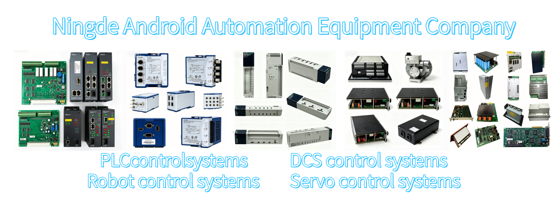
Technical Specifications
Main power supply: Three-phase AC 230V ± 10%, 50/60Hz; Control power supply is independently powered by a single-phase AC 230V
The DC bus has a rated voltage of 300VDC, with built-in energy consumption braking, continuous braking power of 0.5kW, peak power of 18kW. It supports external large-power braking resistors for expansion.
The PWM carrier frequency is 4kHz, protection level is IP10, and it is limited to sealed installation within the control cabinet.
Environmental conditions: Full-load operation within 0~45℃, environmental humidity 5%~85% without condensation; For altitudes above 1000m, the load is reduced, and the maximum power is 55℃ with forced power reduction.
The overall empty-load loss is 480W, natural air cooling for heat dissipation, dimensions 260×355×60mm, net weight approximately 11kg.
Interface and communication configuration
CON1 feedback interface: Exclusive potentiometer terminal for connection only to Resolver potentiometer signal, unable to directly connect to digital encoder
Reserved card slot: Built-in control board slot in the body, can add RA (±10V analog command) and RL (pulse command) series control cards; bare machine has no DI/DO, communication terminals
CON3 debugging serial port: RS232 interface, connects to Indramat DSM debugging software, used for motor parameter identification, fault reading, and parameter backup
The bare base is factory without command input terminals, all control signals are provided by the rear-mounted control board.
Core functions
The base only handles power inversion, rotary transformer signal acquisition, power supply and hardware protection, and cannot operate independently. It must be equipped with a control card to achieve three-loop closed-loop.
Companion RA board: ±10V analog voltage input, speed/torque control; Companion RL board: AB phase pulses + direction position control
Built-in hardware protection logic: Overvoltage, undervoltage, IGBT overcurrent, module over-temperature, rotary transformer break, phase loss fault locking and triggering fault signals
Reserved motor brake drive circuit, configured by the selected control board to control the start and stop sequence of the brake. Applicable scenarios
Old European injection molding machines, general single-machine CNC lathes, old-fashioned textile equipment, imported single-machine printing equipment maintenance and replacement, original MDD rotary change feedback servo motor modification spare parts.
Operation and maintenance instructions
The cabinet is installed vertically. The driver is provided with a ≥80mm gap for heat dissipation on the top and bottom. The power cables and rotary change feedback cables are routed separately in different slots to reduce interference.
The R base cannot be directly replaced with the DS/DL digital feedback base. The feedback hardware circuit is not universal; the optional control board is only available for the RA/RL series, and the DS/DA digital board cannot match the rotary change circuit.
Wear and tear parts: power IGBT module, rotary change feedback socket, built-in auxiliary switch power supply
Maintenance cycle: Clean the cabinet dust every six months, tighten the power connection terminals, check the integrity of the shielding layer of the rotary change cable; power-on debugging of parameters can only be performed after installing the control board.
Get a Quote