CACR-PRA5AA4AH
Never perform wiring or open the drive cover while power is supplied. High voltage inside may cause electric shock or fatal injury. Confirm main power is fully disconnected and wait at least 10 minutes before maintenance to discharge internal capacitor residual voltage. Connect PE terminal to reliable protective earth ground strictly per local electrical codes to avoid equipment damage and safety hazards. Do not use the unit beyond specified ambient temperature and power rating to prevent overheating, fire or permanent breakdown.
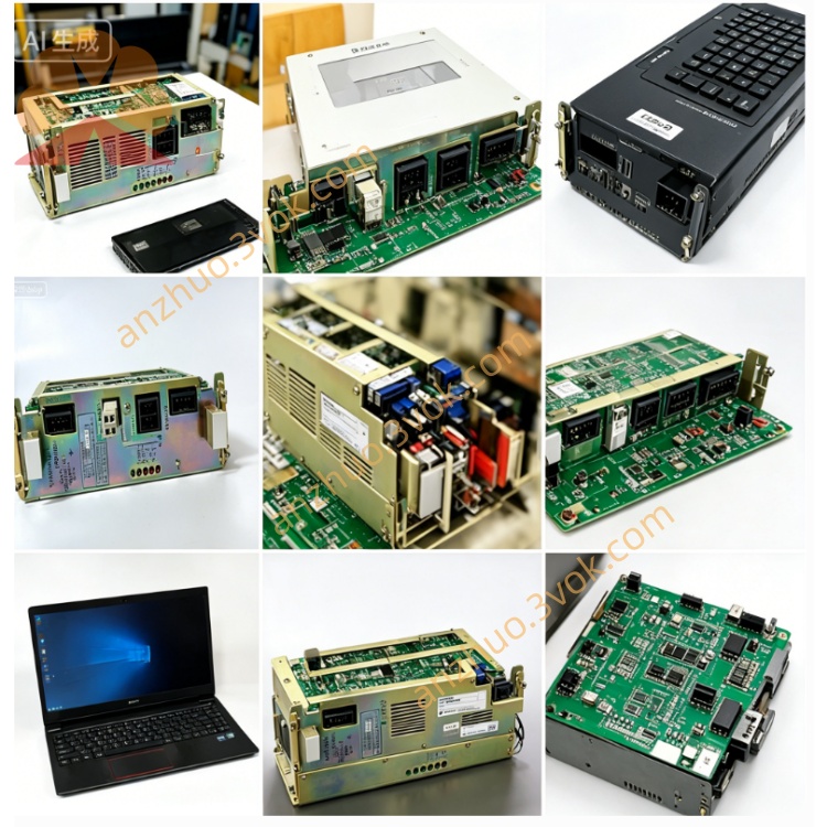
Description
1. SAFETY PRECAUTIONS
WARNING
Never perform wiring or open the drive cover while power is supplied. High voltage inside may cause electric shock or fatal injury. Confirm main power is fully disconnected and wait at least 10 minutes before maintenance to discharge internal capacitor residual voltage. Connect PE terminal to reliable protective earth ground strictly per local electrical codes to avoid equipment damage and safety hazards. Do not use the unit beyond specified ambient temperature and power rating to prevent overheating, fire or permanent breakdown.
CAUTION
Install the SERVOPACK inside sealed electrical cabinet only. Avoid installation in dusty, corrosive gas, flammable vapor or high condensation environment. Keep ambient relative humidity below 90% without dew formation during operation.
2. PRODUCT OVERVIEW
CACR-PR44BCAF is rack-mounted digital AC SERVOPACK under Yaskawa CACR-PR BC series, rated 4.4kW, 200VAC input class for precise positioning control system, matched exclusively with Yaskawa USAFED, USASEM incremental encoder servo motors for CNC and automation equipment positioning applications. This unit supports dual control modes: full closed-loop position control and closed-loop speed control with differential A/B/Z phase encoder feedback interface.
3. MAIN SPECIFICATIONS
Rated input power: single/three-phase AC200V ±10%, 50/60Hz. Rated output current: 28A RMS. Protection grade IP20, natural air cooling. Operating ambient temperature range 0°C ~ +55°C, storage temperature -20°C ~ +70°C. Max installation altitude below 1000m above sea level, no derating required under standard altitude. Insulation resistance ≥10MΩ with 500VDC test, dielectric withstand voltage 1500VAC for 1 minute between power circuit and chassis ground. Built-in multi-protection functions including overcurrent, overvoltage, undervoltage, overload, overspeed, encoder failure and overheat protection.
4. TERMINAL & CONNECTOR DEFINITION
Main Power Terminals
R, S, T: AC main power input terminals connecting 200VAC supply source. U, V, W: three-phase AC output terminals directly wired to matched servo motor stator winding. P, N: external regenerative braking resistor connection terminals for high frequent deceleration working condition. PE: protective earth ground terminal connected to cabinet earth bar.
CN1 Control Signal Connector
CN1 is command and digital input/output interface for upper controller connection. Input signals contain CW/CCW pulse command, servo ON enable, alarm reset, home origin search, external emergency stop signal; pulse input supports line driver differential signal or open-collector signal format. Output signals include servo ready status, fault alarm contact, positioning completion signal and zero-speed detection output.
CN2 Encoder Connector
CN2 connects servo motor incremental encoder cable, pin definition includes differential A, /A, B, /B, Z, /Z feedback signals, +5VDC encoder power supply and signal ground wire, strictly match original motor encoder wiring sequence.
5. INSTALLATION & WIRING GUIDE
Mount the unit on standard cabinet DIN rack frame, reserve minimum 50mm empty space on top and bottom of drive for heat dissipation to guarantee normal cooling effect. Separate high-power power cable (R/S/T/U/V/W) and low-voltage control cables (CN1, CN2) into different wiring ducts to eliminate electromagnetic interference between power and control circuits. If equipment runs with frequent rapid acceleration and deceleration, connect specified external braking resistor between P and N terminals to consume regenerative energy and avoid overvoltage alarm. Complete reliable PE grounding before power-on test run.
6. PARAMETER SETTING DESCRIPTION
Pn000: control mode selection parameter; set value 0 = position control mode, set value 1 = speed control mode.Pn101: electronic gear ratio parameter, adjust pulse scaling ratio to define mechanical moving distance per external input command pulse, core parameter for positioning precision calibration.Pn200 & Pn201: speed loop proportional gain and integral gain, adjust these two parameters to optimize motor running smoothness and dynamic response speed.Pn300: position loop proportional gain for positioning response and stop precision tuning.Pn5xx group parameters: fault alarm configuration and protection threshold setup for overcurrent, overload and overheat trigger value adjustment.
7. COMMON ALARM TROUBLESHOOTING
Overcurrent alarm: check U/V/W motor wiring short circuit, motor winding damage or parameter gain set excessively high.Overvoltage alarm: verify input supply voltage out of tolerance or missing external braking resistor under frequent deceleration load.Encoder error alarm: inspect CN2 encoder cable loose connection, broken wire or encoder component failure on servo motor side.Overheat alarm: check cabinet ventilation blocking, ambient temperature over limit or continuous long-time overload operation.
8. MAINTENANCE INSTRUCTION
Regularly clean dust accumulation on drive ventilation gap every three months to avoid poor heat dissipation. Check all terminal screw tightness periodically to prevent loose wiring caused by equipment vibration. Replace aging braking resistor and damaged signal cable once abnormal heating or signal dropout occurs. All maintenance work must cut off main AC power supply in advance and follow safety rules.
Get a Quote