CACR-PR30BCAF
Read all safety instructions before installation and power-on. Disconnect main power and wait at least five minutes before opening the unit cover to avoid electric shock from residual DC voltage inside the driver. Do not wire or modify connections while power is applied. The unit is IP20 indoor cabinet installation only; avoid dusty, humid, corrosive or flammable gas environment. Secure PE terminal to protective earth strictly as specified.
Description
1. PRODUCT SPECIFICATION
CACR-PR15BCAF belongs to Yaskawa M/F/S series rack-mounted AC Servopack with rated output power 1.5kW. Rated input is three-phase AC 200V~230V, 50/60Hz. Three control modes are available: position closed-loop control, speed closed-loop control and torque closed-loop control. Matching servo motors are Yaskawa USAEMD, USAFED and USASEM series motors equipped with incremental encoders.
Operating ambient temperature ranges 0°C to 40°C; storage temperature is -20°C to 65°C. Working humidity is 5%~90%RH without condensation. Standard applicable altitude is below 1000m above sea level, output power derating is required when used over 1000m elevation.
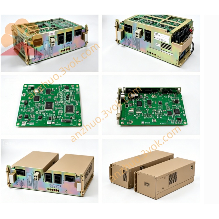
2. MAIN CIRCUIT TERMINAL DEFINITION
R, S, T terminals connect three-phase AC input main power source. U, V, W terminals are output ports wired to three-phase power terminals of matched servo motor. Two polarity-marked terminals are reserved for external regenerative braking resistor connection to consume regenerative energy during motor deceleration. PE terminal must connect reliable protective grounding wire.
3. CONTROL CONNECTOR FUNCTION
CN1 is dedicated encoder connector, used for incremental encoder wiring including A-phase, B-phase, Z-phase signal and +5VDC encoder power supply circuit.CN2 is universal digital and analog I/O connector. Input signals include external pulse position command, servo enable input, fault reset input, analog speed reference and analog torque reference. Output signal is servo fault alarm contact signal for external interlock protection.CN3 is RS232/RS485 serial communication port, which connects PC and Yaskawa SigmaWin parameter setting software to read, modify and back up internal servo parameters.
4. INSTALLATION & WIRING REQUIREMENT
Install the driver onto standard DIN rack inside electrical cabinet. Separate high-power motor cables and low-voltage control signal cables with more than 30cm distance to reduce electromagnetic interference. All shielded control cables shall single-end ground at cabinet grounding bar. Confirm full wiring correctness and ground continuity before first energization.
5. POWER-ON AND TRIAL RUN PROCEDURE
Complete motor parameter matching according to actual motor model after power supply. Set control mode, loop gain and command signal type in corresponding parameter codes step by step. Execute no-load jog operation first to verify rotation direction and running stability before full-load test run.
6. FAULT DIAGNOSIS & MAINTENANCE
When alarm code displays on unit indicator, cut off input power first then check possible causes including wrong wiring, overload load, improper parameter setup or encoder circuit breakdown. Regularly clean dust on driver ventilation gap during long-term operation; replace aging regenerative resistor if abnormal overheating occurs.
7. STORAGE CONDITION
Store unused Servopack in dry, room-temperature environment away from direct sunlight and vibration. Prevent moisture infiltration to circuit board and terminal components during long-term stocking.
Get a Quote