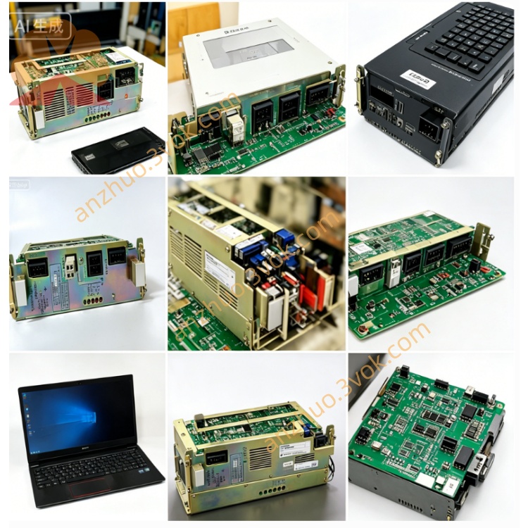
CACR-PR10BCAF
CACR stands for Yaskawa AC digital servo drive series designation. PR denotes rack-mounted positioning dedicated driver matched with corresponding positioning control unit. 10 represents the rated power specification of 1.0 kilowatt. B refers to the defined hardware version and internal power circuit structure. C means dual closed-loop control configuration including speed loop and position loop. AF indicates incremental encoder feedback interface plus integrated built-in regenerative braking accessory configuration.
Description
1. Model Code Explanation
CACR stands for Yaskawa AC digital servo drive series designation. PR denotes rack-mounted positioning dedicated driver matched with corresponding positioning control unit. 10 represents the rated power specification of 1.0 kilowatt. B refers to the defined hardware version and internal power circuit structure. C means dual closed-loop control configuration including speed loop and position loop. AF indicates incremental encoder feedback interface plus integrated built-in regenerative braking accessory configuration.
2. Technical Specifications
For power parameters, the drive accepts three-phase alternating current input ranging from AC200V to 230V with 50Hz and 60Hz applicable. Its rated output power is 1.0kW and rated output current is 6.0 amperes, with internal DC bus voltage maintained between DC280V and DC320V.In environmental specifications, the permissible operating ambient temperature ranges from 0°C to +55°C, while storage temperature covers -20°C to +70°C. Working relative humidity is limited between 5% and 90% without condensation, and its enclosure protection level is IP20 designed for cabinet installation only. It is fixed by standard DIN rail vertical mounting, with approximate net weight of 3.2 kilograms.Regarding control performance, it adopts sine-wave PWM vector control method. The adjustable speed range reaches 1:5000 and positioning precision is controlled within ±1 pulse, with maximum control response frequency up to 500Hz.Built-in protection functions contain overcurrent, overvoltage, undervoltage, overheating, regenerative circuit failure, encoder disconnection and main controller abnormal fault protection.
3. Interface and Communication Configuration
Power terminals include R/S/T for three-phase power input, U/V/W for servo motor power output and P/N reserved terminals for external regenerative resistor connection. CN2 connector serves as encoder port to receive differential A/B/Z phase incremental encoder signal matching specified Yaskawa servo motors. CN1 is universal digital I/O terminal block equipped with 8 digital input channels and 6 digital output channels, which can be flexibly set for limit signal, home position detection, drive fault alarm and operation start-stop signal.For communication, standard onboard RS485 interface uses Yaskawa exclusive communication protocol for servo parameter read and write. An optional expansion board supports Modbus-RTU communication protocol. Besides, differential 5V pulse command input interface is equipped with maximum input pulse frequency of 500kpps for external position command control.
4. Core Functions
It supports multiple control modes including position control, speed control and hybrid switchable control. Closed-loop feedback from encoder realizes high-precision positioning and stable speed regulation. Integrated regenerative braking circuit handles motor energy feedback during deceleration to save extra external braking resistance in most regular working conditions. Parameter modification via communication or local panel realizes flexible tuning of gain, acceleration and deceleration parameters to fit varied load demands. Comprehensive fault self-diagnosis can automatically lock output and send alarm signal once abnormal status occurs to protect the whole driving system.
5. Applicable Scenarios
This servo drive is widely applied in automated precision machining equipment, automatic packaging machinery, electronic component assembly equipment, small gantry positioning platforms and textile automatic feeding mechanisms. It fits equipment requiring stable low-speed operation and accurate fixed-point positioning under medium load condition.
6. Operation and Maintenance Instructions
Before power-on, check all wiring of power cable, encoder wire and I/O signal line to eliminate short-circuit or wrong connection risks. Complete relevant parameter setup according to matched motor model and mechanical load requirement prior to formal operation.During daily use, keep installation cabinet well ventilated to avoid dust accumulation blocking heat dissipation vents. Regularly inspect terminal screw tightness and cable insulation condition every three to six months. Cut off main power supply completely before any wiring modification or internal maintenance. Stop equipment operation immediately and cut off power when persistent fault alarm appears, inspect related motor, wiring and mechanical load before restarting operation.
Get a Quote