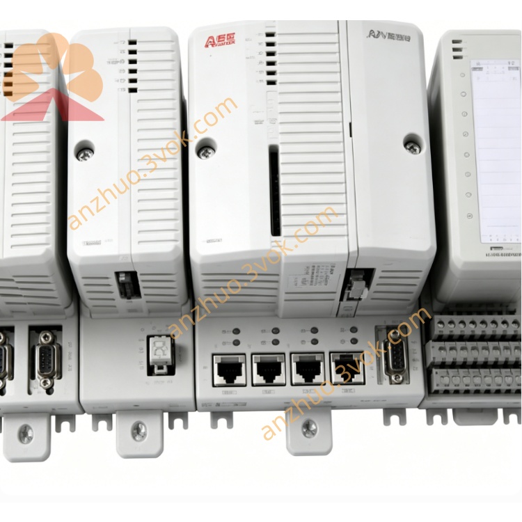
ABB 1TNE968902R2301(DX561)DX561 mixed digital input/output module
This unit is DX561 mixed digital input and output module of ABB S500 series, compatible with AC500 and AC500-eCo PLC control systems. Manufactured in accordance with IEC industrial standards and ABB global production specifications, it features compact DIN rail mounted structure integrating 8 digital input channels and 8 transistor digital output channels in a single unit. With non-contact transistor output design, the module brings high switching frequency and zero mechanical abrasion, helping optimize cabinet layout and reduce installation space for discrete automation projects.
Description
1.Product Brief Introduction
This unit is DX561 mixed digital input and output module of ABB S500 series, compatible with AC500 and AC500-eCo PLC control systems. Manufactured in accordance with IEC industrial standards and ABB global production specifications, it features compact DIN rail mounted structure integrating 8 digital input channels and 8 transistor digital output channels in a single unit. With non-contact transistor output design, the module brings high switching frequency and zero mechanical abrasion, helping optimize cabinet layout and reduce installation space for discrete automation projects.
2.Model Definition Explanation
1TNE serves as unified coding prefix for ABB low voltage automation spare parts used for global ordering and product classification management.9689 is internal catalog grouping code representing S500 series PLC I/O module product range.02 stands for upgraded optimized hardware base version compared with the early original design.R refers to factory fully tested standard finished configuration defined by ABB internal component coding regulations.2301 is exclusive configuration code corresponding to DX561 specification with 8DI plus 8DO transistor layout, which differs from independent digital input modules and single-type output modules in circuit structure and channel allocation.
3.Technical Specifications
Rated operating power supply is DC24V ranging from 20.4VDC to 28.8VDC, and typical power consumption is 2.3W. It contains 8 channels of DC24V digital input supporting sink and source wiring mode with single channel input current of 5mA and 8ms input response delay. The 8-channel NPN transistor DC24V output provides 0.5A rated load per channel, supporting maximum switching frequency of 100Hz without mechanical wear. Working ambient temperature ranges from 0℃ to +60℃, storage temperature covers -40℃ to +70℃, and protection grade is IP20 for inner cabinet installation. Each channel is equipped with independent LED status indicator, and the whole module passes IEC61000 EMC anti-interference certification.
4.Interface and Communication Configuration
The rear side is equipped with dedicated backplane plug-in bus connector to dock with S500 base rack and realize high-speed data interaction with PLC CPU via internal rack bus without extra external communication wiring. Front panel is configured with pluggable HE10 terminal block for external wiring of field sensors and DC loads. All data transmission relies on system internal backplane bus, and fieldbus protocols such as Modbus or Profinet can be realized by matching external system communication adapter, with no independent external fieldbus port arranged on module housing.
5.Core Functions
It achieves bidirectional data exchange with PLC main controller through backplane bus. Input channels collect switching signals from field proximity switches, limit switches and photoelectric sensors and transmit digital status data to CPU for logic processing. Output channels receive control commands from CPU and drive internal transistors to realize on-off control for external DC solenoid valves, indicator lamps and small DC contactors. The module monitors overload and short-circuit faults of output loops in real time and automatically uploads corresponding fault information to upper PLC for alarm notification and field troubleshooting.
6.Application Scenarios
It is widely installed inside PLC control cabinets of food packaging equipment, logistics conveyor lines, mini water treatment facilities, textile automated production lines and HVAC fan and pump control systems. The module is preferred for application sites requiring both on-site signal collection and small DC load driving, which can cut down the total quantity of installed modules and save cabinet layout space versus separate deployment of DI and DO modules.
7.Operation and Maintenance Instructions
Inspect backplane plug and front terminal block for cracks or deformation before installation, and confirm correct DC24V power polarity to prevent component damage from reverse connection. Fix the module onto standard 35mm DIN rail and insert into the specified base slot, then complete field wiring strictly according to printed channel marking on module surface. Perform routine maintenance every six months and remove dust accumulated on casing and terminals with dry soft brush while forbidding liquid cleaning agents. Replace the whole module directly if continuous channel faults remain after eliminating external circuit problems, and unauthorized disassembly or modification of internal circuit is prohibited.
Get a Quote