
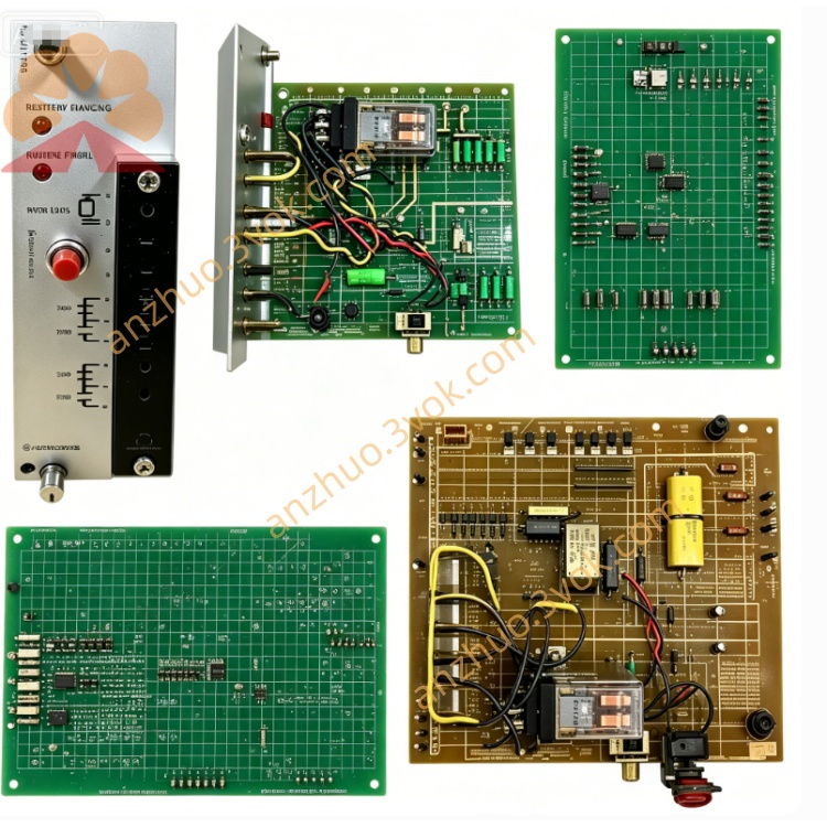
Reliance Electric 45C69 dual dry contact (relay) output module
Description
Product Introduction
Model Interpretation
45C: Denotes the AutoMax series I/O module family.
69: Indicates dual isolated dry contact outputs (low‑power relay type), distinct from higher‑power 45C66/66A.
No suffix denotes standard revision; functionally fixed within the 45C series.
Technical Parameters
Output channels: 2 independent, isolated normally open (N.O.) dry contacts.
Maximum voltage: 125 VAC; 30 VDC.
Maximum current: 0.3 A AC per channel; 1 A DC per channel (resistive load).
Isolation: Full electrical isolation between channels and system logic.
Status indicators: LED for power, each channel ON/OFF, and fault.
Fuse: None (low‑power design, electronic overcurrent protection).
Operating temperature: ‑20 °C to +60 °C.
Protection class: IP20 (cabinet mounting).
Mounting: 45C‑series DIN rail.
Dimensions (W×H×D): 110 × 60 × 67 mm; weight: 0.14 kg.
Certification: CE, UL (industrial control standards).
Lifespan: Mechanical relay life >100,000 operations.
Interface and Communication Configuration
Connection: Plug‑in to AutoMax backplane for power and logic signals.
External wiring: Screw terminals for two dry contacts and common points.
Communication: Backplane bus only; no external communication ports.
Compatibility: AutoMax PLC systems, Mark VI series compatible.
Core Functions
Converts control logic signals into dry contact switch actions for low‑power loads.
Provides galvanic isolation between controller and field circuits to suppress noise and prevent damage.
Electronic overcurrent protection safeguards the module and connected devices.
Real‑time LED status for quick diagnostics and operation monitoring.
Application Scenarios
Industrial automation: Driving small relays, indicator lamps, buzzers, and low‑power solenoids.
Low‑current switching: 120 VAC or 24 VDC loads in machine tools, packaging, and process equipment.
Safety and signal isolation: Isolated on/off control in safety circuits and interlock systems.
Operation and Maintenance Instructions
Install on a 45C‑series DIN rail and ensure full engagement with the backplane.
Verify all external wiring is tight and insulated before powering on.
During operation, check LED indicators regularly for normal status.
Keep the module surface clean and free of dust to ensure proper heat dissipation.
Disconnect system power before removal, inspection, or replacement.
Do not disassemble internal components; replace the entire module if permanent failure occurs.
The module is discontinued by the manufacturer; use surplus or refurbished units for replacement。
Get a Quote