
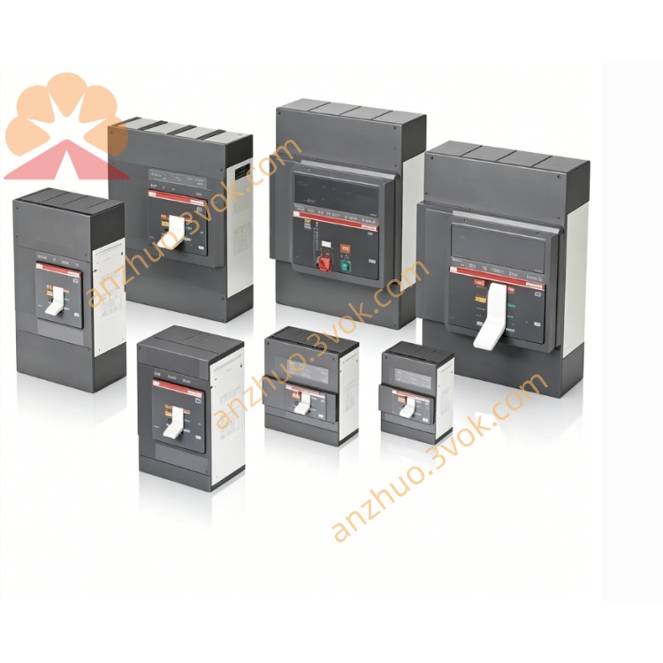
ABB 1SBP260013R1001( 07KR51) basic programmable logic controller
ABB 1SBP260013R1001, commercially named 07KR51, is a basic programmable logic controller of the Advant Controller 31 series. It is powered by 24 V DC and equipped with relay outputs. This compact unit integrates CPU, power supply, digital inputs and outputs as a whole. It features stable performance and reliable switching control, and is widely used for small and medium-sized automation systems and distributed I/O applications.
Description
Product Introduction
ABB 1SBP260013R1001, commercially named 07KR51, is a basic programmable logic controller of the Advant Controller 31 series. It is powered by 24 V DC and equipped with relay outputs. This compact unit integrates CPU, power supply, digital inputs and outputs as a whole. It features stable performance and reliable switching control, and is widely used for small and medium-sized automation systems and distributed I/O applications.
Model Interpretation
1SBP is the unified part number prefix for ABB AC31 and Procontic CS31 series controllers. 260013 is the base model code for the 24 V DC controller with relay outputs. R1001 stands for the standard hardware revision. 07KR51 is the commercial designation of this AC31 basic control unit.
Technical Parameters
This controller belongs to ABB Advant Controller 31 series and is compatible with Advant OCS systems. It has 8 channels of 24 V DC digital inputs, which support both sink and source connection modes. The operating current of each input channel is no more than 5 milliamperes, and the input delay ranges from 1 millisecond to 7 milliseconds. It is fitted with 6 relay output channels. Each relay channel can work under 250 V AC or 30 V DC with a rated load current of 5 amperes, and the mechanical service life reaches more than 100 thousand operations. The rated power supply is 24 V DC with a tolerance of plus or minus 10 percent. The power consumption is 5 watts when working alone and 10 watts when connecting with expansion modules. The processor operates at 400 kilohertz. It is configured with 34 kilobytes program memory and 4.4 kilobytes data memory supported by backup battery. Two built-in hardware high-speed counters support maximum input frequency up to 5 kilohertz, and an integrated real-time clock is available for timing and data timestamp. The operating temperature ranges from 0 degree Celsius to 55 degree Celsius, and the storage temperature ranges from minus 40 degree Celsius to 70 degree Celsius. The protection class is IP20 for cabinet installation. The device can be mounted on standard DIN rail or fixed with screws. The overall dimensions are 102 millimeters by 102 millimeters by 127 millimeters and the weight is approximately 0.4 kilograms. The product has obtained CE and UL certifications.
Interface and Communication Configuration
Screw terminals are adopted for connecting 8 digital input channels, 6 relay output channels and 24 V DC power supply. A standard RS-232 port is reserved for program uploading and downloading, ASCII communication and Modbus RTU data transmission. The built-in CS31 bus based on RS-485 technology can connect up to 31 remote I/O devices, expanding the total I/O points of the whole system to around 1000. Multiple LED indicators display power status, running status, fault alerts and working status of each channel. This controller is fully compatible with all analog and digital I/O modules of AC31 series for system function expansion.
Core Functions
It realizes integrated logic control to connect on-site sensors, switches and various actuators directly. The relay outputs provide strong load driving capability to drive solenoid valves and small motors without additional intermediate relays. The built-in high-speed counters and real-time clock meet the requirements of accurate counting and timing control. The CS31 field bus ensures stable long-distance data transmission with remote I/O modules without affecting the operation of the main controller. The battery-backed memory can retain user programs and key data after power failure. It supports channel-level fault detection and real-time status indication to help operators quickly locate and eliminate faults.
Application Scenarios
It is applied to small production lines, assembly equipment and material handling systems in factory automation. It is suitable for air conditioning units, fan coil units and environmental monitoring in building automation and HVAC systems. It is used for pump operation, valve control and signal monitoring in water treatment and wastewater treatment projects. It is an ideal control unit for packaging machinery with switching signal control demands. It also serves as a compact control core for textile, woodworking and other general OEM mechanical equipment.
Operation and Maintenance Instructions
Install the controller vertically on standard DIN rail and keep enough clearance on the top and bottom for heat dissipation. Place the device away from intense vibration, moisture and corrosive gas. Use qualified copper wires for wiring and fasten all terminals firmly. Check the polarity of 24 V DC power supply strictly and do not exceed the rated load of relay channels. Complete programming and parameter configuration via ABB AC31GRAPH or supporting configuration software. Inspect terminal tightness and LED indicator status regularly during operation. Clean dust on the surface with dry cloth. Replace the backup battery every 3 to 5 years to guarantee normal operation of memory and real-time clock. Cut off the power supply completely before any disassembly and maintenance work. Do not run the device with damaged wires or open housing.
Get a Quote