
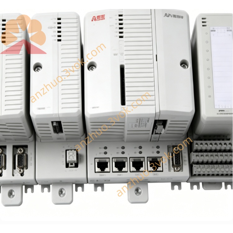
ABB 1SAP284100R0001 (DX581‑S) SIL3‑certified safety digital I/O module
ABB 1SAP284100R0001, also named DX581-S, is a safety digital combined input and output module of S500-S safety I/O series for ABB AC500-S safety PLC system. It is equipped with 8 safety digital input channels and 8 safety digital output channels. The product has passed SIL3 safety certification, and is specially developed for safety related control applications in industrial sites. It features reliable performance, complete safety protection mechanisms and strong anti-interference capability, meeting strict functional safety standards.
Description
Product Introduction
ABB 1SAP284100R0001, also named DX581-S, is a safety digital combined input and output module of S500-S safety I/O series for ABB AC500-S safety PLC system. It is equipped with 8 safety digital input channels and 8 safety digital output channels. The product has passed SIL3 safety certification, and is specially developed for safety related control applications in industrial sites. It features reliable performance, complete safety protection mechanisms and strong anti-interference capability, meeting strict functional safety standards.
Model Interpretation
1SAP represents the general series code of ABB S500 I/O modules. 2841 stands for module type, which refers to combined safety digital input and output module with 8 safety inputs and 8 safety outputs. 0001 indicates standard hardware version and revision. DX581-S is the commercial model name. DX means digital input and output module, the digit 5 means it is compatible with AC500 PLC platform, 81 refers to safety module type, and S marks it as safety series product.
Technical Parameters
The module is configured with 8 safety digital input channels and 8 safety digital output channels. The input supports 24 VDC working voltage within the range of 20.4 VDC to 28.8 VDC, and the input current of each channel is 7 mA. The input part can be set to 8 channels SIL2 mode or 4 channels SIL3 mode through software. Each safety digital output channel adopts 24 VDC power supply, with single channel load capacity of 0.5 A and built-in short circuit protection function. The product complies with IEC 61508 SIL3, ISO 13849-1 PLe and EN 954-1 Category 4 safety standards. Galvanic isolation is adopted between field circuit and backplane bus, and the isolation voltage can reach 2500 V AC. The overall signal response time is less than 1 millisecond, and the input debounce time can be adjusted from 1 millisecond to 500 milliseconds. Four channels support pulse output, which is used for safety circuit detection. The working power is 24 V DC with a tolerance of ±10%, and the total power consumption is no more than 3 W. The operating temperature ranges from minus 25 degrees Celsius to 60 degrees Celsius. The protection class of the module shell is IP20. The overall dimensions are 67.5mm in width, 76mm in height and 62mm in depth, and the weight is 0.163kg. It is installed on standard 35mm DIN rail.
Interface and Communication Configuration
The field connection part adopts screw terminal blocks, with independent terminals for 8 input channels and 8 output channels, and each terminal is clearly labeled for wiring operation. The module is directly connected to the safety bus of AC500-S PLC through the backplane interface to realize high-speed data interaction with the main controller. It supports mainstream safety and industrial communication protocols including PROFIsafe, PROFIBUS DP and PROFINET by matching the communication expansion ports of PLC. Multiple LED indicators are arranged on the module surface, including green power indicator, yellow running indicator, channel status indicators, red fault indicator and green safety status indicator, which can display the working state of the module and each channel in real time.
Core Functions
It integrates safety signal collection and safety control output functions, which can access field safety sensors such as emergency stop switches and safety doors, and drive safety actuators at the same time. It supports flexible safety level configuration to adapt to different safety design requirements of on-site systems. The built-in pulse output function can complete active detection of safety sensors and circuits, and effectively discover potential faults in advance. The comprehensive fault diagnosis function can monitor open circuit, short circuit and overvoltage of each channel, as well as internal operating temperature, and upload all fault information to the PLC system. The dual redundant design and safety protection mechanism ensure the stable and reliable operation of safety circuits under various working conditions.
Application Scenarios
It is widely used in safety instrumented systems of petroleum, chemical and process industries to realize emergency shutdown and safety interlock control. It applies to mechanical equipment production lines, packaging equipment and machine tool systems for safety protection of equipment operation. It is used in factory automation and material handling occasions to monitor safety protection devices and execute safety control actions. It is also suitable for various industrial sites that need to meet high-level functional safety standards.
Operation and Maintenance Instructions
Install the module on standard 35mm DIN rail inside the control cabinet. Keep a gap of 20mm around the module for heat dissipation, and avoid installation in environments with severe vibration, corrosive gas, excessive dust and humidity. Use standard cables for safety signal wiring, separate signal cables from power cables to avoid electromagnetic interference, and control the tightening torque of terminal screws between 0.5Nm and 0.6Nm. Complete safety mode, channel parameters and safety logic configuration through supporting configuration software, and verify the operating state via indicator lights after program download. Conduct regular daily inspection work, periodically check the firmness of wiring and the cleanliness of terminals. When cleaning the module, only use dry cloth to wipe the surface, and do not use liquid cleaning agents. If the power indicator is off, check the 24 VDC power supply and connecting lines. If the running indicator flashes abnormally, recheck and download the configuration program. If the fault indicator is on, troubleshoot open circuit, short circuit or overvoltage faults of channels and field equipment. Cut off the total power supply of the system before replacing the module, disconnect all connecting lines, remove the faulty module and install a new one, then reconnect the lines and complete parameter configuration again. Store the module in dry and cool environment with original packaging, and avoid strong vibration and collision during transportation.
Get a Quote