
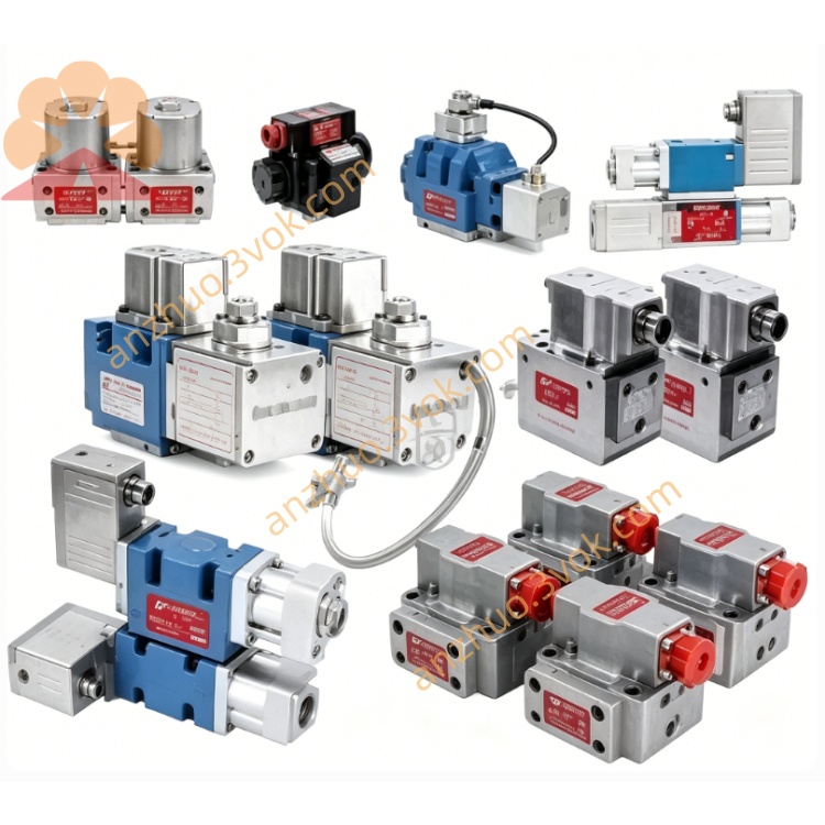
MOOG D661-4651 Two-Stage ServoJet Electro-Hydraulic Servo Valve with Integrated LVDT Spool Closed-Loop Feedback
Description
Model Definition
D661: Series code, featuring integrated electronics, 24VDC power supply and NG10 installation
4651: Spool and sleeve assembly, rated flow 30 L/min at 35 bar pressure drop
Technical Specifications
Hydraulic Parameters
Rated flow: 30 L/min (ΔP=35 bar)
Maximum operating pressure: 350 bar for port P/A/B; 210 bar for internal drain port T, 350 bar for external drain port T
Step response: 6.5–14 ms (0 to 100% stroke at 210 bar)
Hysteresis: Less than 0.2%
Resolution: Less than 0.1%
Temperature drift: Less than 1.5% (ΔT=55K)
Null leakage: Less than 8 mL/min
Electrical Parameters
Power supply: 24 VDC (18–32 VDC)
Control signal: ±10 V or ±10 mA
Feedback signal: 4–20 mA for spool position via LVDT
Electrical connector: 6+PE, IP65 protection grade
Physical & Environmental Parameters
Operating temperature: -40℃ to +85℃
Weight: Approximately 5.1 kg
Interface & Communication Configuration
Hydraulic interface: Four ports P/A/B/T in accordance with ISO 4401-05 standard
Electrical interface: Power terminals for 24VDC, GND and PE; command signal terminals for ±10V/±10mA; 4–20mA position feedback terminals and status alarm terminals
Core Functions
ServoJet pilot stage: Excellent contamination resistance, low null drift and long service life
Integrated closed-loop amplifier: Built-in PID control, dead zone compensation and overload protection
LVDT spool position feedback: Ensures high precision and linearity throughout the full stroke
Fail-Safe design: The spool returns to neutral position when power cuts off to guarantee equipment safety
Application Scenarios
Metallurgy: Mini AGC roll gap control and tension control
Test equipment: Material testing machines, fatigue test benches and small vibration tables
Industrial automation: Precision machine tools, injection molding machines and hydraulic forming equipment
Heavy industry & energy: Wind turbine pitch control, auxiliary control for shield machines and marine steering gears
Usage & Maintenance
Installation: Mount horizontally or vertically and keep away from severe vibration. The hydraulic fluid cleanliness shall meet NAS 1638 Class 6 or higher.
Commissioning: Supply 24VDC power and connect ±10V/±10mA command signal. Perform null adjustment and gain calibration according to 4–20mA position feedback.
Maintenance: Regularly inspect the contamination level of hydraulic fluid. Calibrate null position and gain every 6 months. Avoid long-time standby under high pressure without command signal.
Get a Quote