
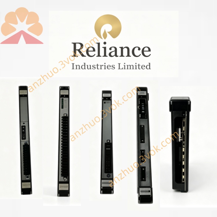
Reliance 45C207 (45C-207)
Description
Product Description
Model Number Interpretation
45C: Prefix for Reliance AutoMate 45C series PLC/drive modules.
207: Designates a gate driver interface module (distinct from 203 = serial comms, 204A = redundancy processor).
Hyphen: Common industrial part‑number formatting (45C-207 = 45C207).
No suffix: Indicates original hardware revision (no A/B/C upgrades).
Technical Specifications
Power Supply: 24VDC via backplane or dedicated auxiliary input.
Input Logic: 5VDC or 24VDC logic‑level control signals.
Gate Output: ±15V to ±20V adjustable; peak current up to 5A for fast switching.
Isolation: 2500V RMS dielectric strength (control ↔ power side).
Switching Frequency: Up to 20kHz for high‑speed drive applications.
Channels: Dual‑channel (supports half‑bridge or single‑phase drives).
Temperature: 0°C to 55°C (industrial operating range).
Mounting: Single‑slot, DIN‑rail compatible for 45C series racks.
Weight: ~0.55kg; compact metal enclosure for noise immunity.
Interface and Communication Configuration
Backplane Interface: Connects to AutoMate 45C series PLC/drive backplanes for power and control signal exchange.
Control Inputs: Two isolated logic inputs (IN1, IN2) for PWM/on‑off commands from the main CPU.
Gate Outputs: Two isolated gate drive outputs (OUT1, OUT2) for direct connection to IGBT/MOSFET gates.
No Serial/Network Ports: All configuration is hardwired or set via the main system controller; no independent communication ports.
Compatibility: Exclusively for AutoMate 45C and AutoMax drive systems; not compatible with 20/30/40 series PLCs.
Core Functions
Signal Isolation: Provides galvanic isolation between low‑voltage control logic and high‑power circuits, preventing damage from voltage spikes and ground loops.
Level Shifting: Converts 5V/24V logic signals to high‑amplitude (±15–20V) gate pulses required for power semiconductor switching.
Current Amplification: Delivers high peak current to gate terminals, ensuring fast, clean switching and minimizing power device losses.
Fault Protection: Integrates over‑current and under‑voltage lockout (UVLO) to shut down outputs during faults, protecting the drive system.
Noise Suppression: Filters and conditions control signals to reject EMI/RFI in harsh industrial environments.
Application Scenarios
High‑Power Motor Drives: Used in AC/DC variable‑frequency drives (VFDs) for conveyors, pumps, compressors, and machine tools.
Power Conversion Systems: Applied in rectifiers, inverters, and UPS systems requiring isolated, high‑speed power switching.
Legacy AutoMate 45C Systems: Replacement part for aging gate driver modules in manufacturing, process control, and material handling equipment.
Critical Industrial Processes: Deployed in oil/gas, water treatment, and pharmaceutical plants where drive reliability and isolation are critical.
Usage and Maintenance Instructions
Installation: Insert firmly into a single slot of the 45C series rack; ensure backplane connectors are fully seated and locked.
Wiring: Connect control inputs (IN1/IN2) to the main CPU’s logic outputs; connect gate outputs (OUT1/OUT2) directly to power semiconductor gates; verify isolation and voltage ratings before powering on.
Power‑On Check: After installation, apply 24VDC power and verify LED status (PWR = on, FAULT = off); check for stable gate output pulses with an oscilloscope.
Routine Maintenance: Quarterly inspections; clean dust from the enclosure and connectors; check wiring tightness and insulation integrity; replace if LEDs indicate persistent faults or output degradation.
Safety: Disconnect all power and allow 5 minutes for discharge before handling; avoid live‑wire maintenance; use only with compatible 45C series backplanes and power devices。
Get a Quote