
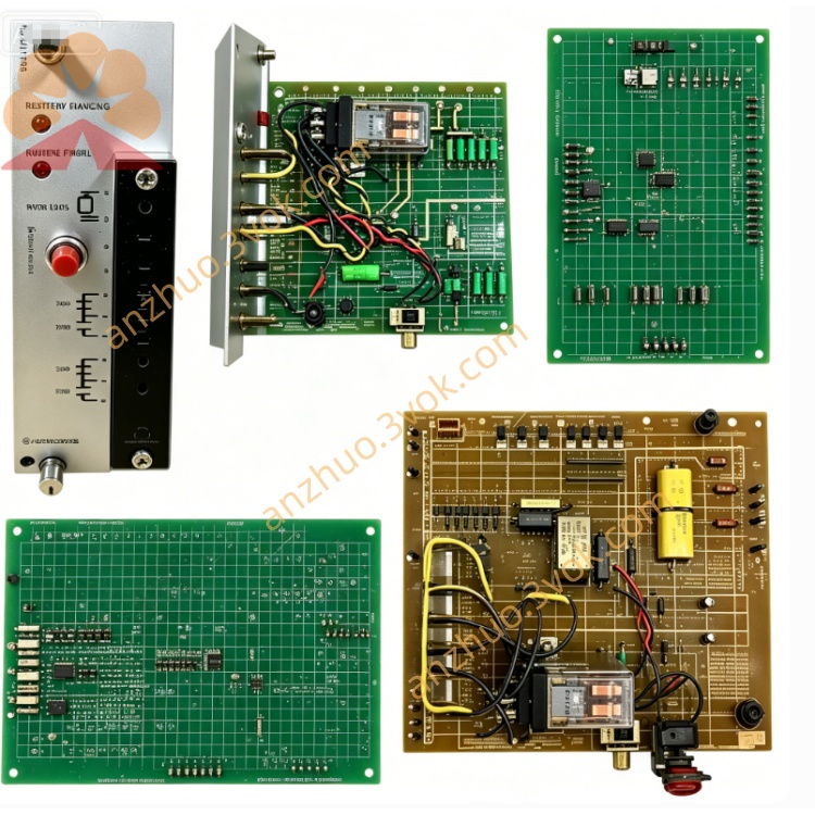
Reliance 29501-1XE
The 29501-1XE is an enhanced high-frequency dynamic brake interface module designed for Reliance Electric GV3000/SE and VTAC7 series AC drives. It connects the DC bus of the drive to external braking resistors to dissipate regenerative energy generated during motor deceleration. This module adopts high-efficiency heat dissipation structure and dual voltage and current control logic, which is suitable for working conditions with frequent start-stop and high-inertia loads. This model has been discontinued by the original manufacturer, and surplus and refurbished units are mainly used for maintenance and retrofit of legacy industrial drive systems.
Description
Product Description
The 29501-1XE is an enhanced high-frequency dynamic brake interface module designed for Reliance Electric GV3000/SE and VTAC7 series AC drives. It connects the DC bus of the drive to external braking resistors to dissipate regenerative energy generated during motor deceleration. This module adopts high-efficiency heat dissipation structure and dual voltage and current control logic, which is suitable for working conditions with frequent start-stop and high-inertia loads. This model has been discontinued by the original manufacturer, and surplus and refurbished units are mainly used for maintenance and retrofit of legacy industrial drive systems.
Model Number Interpretation
29501 is the base part number for the dynamic brake interface module. 1 represents the standard power rating compatible with 5 to 15 HP drives. X stands for enhanced version supporting high-frequency braking cycles. E indicates the module is equipped with optimized heat dissipation design and extended operating temperature range.
Technical Specifications
The applicable DC bus voltage ranges from 540 VDC to 650 VDC, matching 380 to 460 VAC three-phase input drives. The continuous braking power is 1.5 kW, and the peak braking power reaches 4.5 kW under 10 percent duty cycle. It uses non-contact transistor as the switching component. The control logic is combined with voltage and current detection, and the switch closes when DC bus voltage is higher than 50 V and braking current is zero. A built-in LED indicator lights up when braking current exists to show the working status. The product is an open frame PCB type for panel mounting. The operating temperature ranges from -10 degrees Celsius to 60 degrees Celsius. The total weight is approximately 0.6 kg.
Interface and Communication Configuration
DC bus terminals are used to connect DC positive and DC negative ports of the matched AC drive. Dedicated terminals are reserved for connecting external braking resistors. The module integrates independent control logic and requires no additional external control wiring. There is no external communication port, and the operating state can be checked through the onboard LED indicator. All connection terminals adopt screw type for stable wiring.
Core Functions
It converts regenerative electric energy into heat through external resistors to prevent DC bus overvoltage and protect the main drive. The optimized circuit structure supports high-frequency repeated braking actions. The dual detection mechanism of voltage and current ensures stable and reliable braking performance. The visible LED indicator helps operators quickly judge the working state and locate faults. The excellent heat dissipation design ensures long-term stable operation under continuous load.
Application Scenarios
It is compatible with Reliance GV3000/SE and VTAC7 series three-phase AC drives with 380 to 460 VAC input. It applies to industrial equipment with frequent deceleration and high inertia loads such as cranes, centrifuges and large conveyors. It can be used in process production lines, material handling systems and industrial HVAC equipment. It is a standard replacement part for old brake modules in legacy automation systems.
Usage and Maintenance Instructions
Mount the module vertically on the installation panel near the drive, and reserve at least 70 mm space around it for ventilation and heat dissipation. Use standard stranded wires for wiring, and fasten all terminals with specified torque. Before powering on, check the resistance value of external braking resistors and confirm there is no short circuit. Disconnect all power supply and wait for 5 minutes to fully discharge the DC bus before inspection and maintenance. Regularly check whether the terminals are loose or corroded, and clean dust on the circuit board periodically. Do not operate the module beyond the rated temperature range. Store spare products in a cool, dry and dust-free environment. Do not disassemble the module without professional guidance.
Get a Quote