
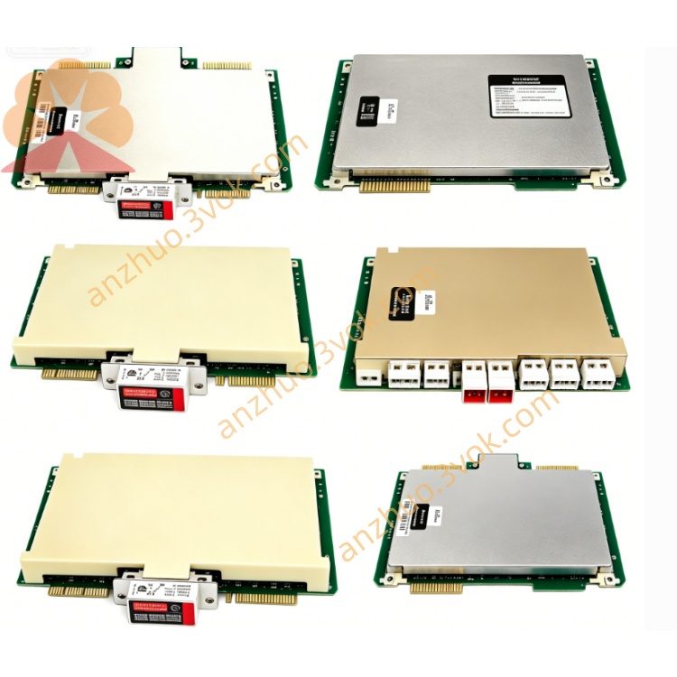
HONEYWELL 51304728-175
Description
Product Description
Model Definition
5130: TDC 3000/UCN DCS series.
4728: Digital Input FTA with galvanic isolation.
175: 16 channels, non‑coated PCB, gold‑plated screw terminals, standard isolation, redundant compatible.
Technical Specifications
Channels: 16 differential digital input channels.
Signal Type: 24 VDC dry contact or active high/low signals.
Isolation: 1500 VAC RMS galvanic isolation (field‑to‑system).
Terminals: Gold‑plated screw terminals (field side); 50‑pin ribbon connector (system side).
Input Voltage: 24 VDC nominal, 18–30 VDC operating range.
Current Draw: ≤10 mA per channel.
Operating Temperature: -20°C to +60°C.
Storage Temperature: -40°C to +70°C.
Humidity: 5%–95% non‑condensing.
PCB Coating: Non‑conformal coated.
Certifications: CE, UL, CSA, RoHS.
Form Factor: Size B, weight approx. 1.2 kg.
Interface and Communication Configuration
System Side: Connects to digital input IOPs (e.g., MC‑PDI02, 51304446‑150) via dedicated 50‑pin ribbon cable.
Field Side: 16 pairs of gold‑plated screw terminals for 24 VDC devices (switches, relays, proximity sensors).
Isolation: Full galvanic isolation blocks ground loops and transient voltages.
Redundancy: Supports dual‑module redundancy for high‑availability systems.
Protocol: Passive FTA; no independent protocol. All signal processing/diagnostics via IOP and DCS.
Core Functions
Provides 16‑channel isolated digital input termination for 24 VDC field devices.
1500 VAC isolation protects DCS from electrical noise, ground loops, and voltage spikes.
Non‑coated PCB for clean, dry industrial environments.
Internal filtering and surge protection enhance signal stability.
Gold‑plated terminals resist oxidation and vibration, ensuring reliable connections.
Drop‑in compatible with TDC 3000/TPS/UCN/Experion PKS; hot‑swap capable.
Application Scenarios
Systems: Honeywell TDC 3000, TPS, UCN, Experion PKS DCS.
Industries: Oil & gas, chemical, petrochemical, power generation, pharmaceutical, pulp & paper, general manufacturing.
Field Devices: Limit switches, pressure switches, level switches, proximity sensors, relay contacts.
Installation: DCS control room cabinets, clean/dry local panels (non‑corrosive, low dust).
Usage and Maintenance Instructions
Usage
Mount in standard DCS cabinet with sufficient wiring and ventilation space.
Connect 50‑pin ribbon cable to matching digital input IOP; fully seat and lock.
Wire field devices to designated terminals, observing polarity; tighten to 0.8–1.0 N·m.
Power on DCS, verify no fault alarms, and confirm input status accuracy before operation.
Maintenance
Keep environment clean, dry, and well‑ventilated.
Inspect terminals and cables quarterly for tightness, corrosion, or damage; replace worn parts.
Clean PCB and terminals only with dry soft cloth; no liquids or abrasives.
Store spares in anti‑static bags in cool, dry area.
Use ESD wristbands/mats during handling to prevent static damage.
Do not disassemble; repairs by authorized personnel only。
Get a Quote