
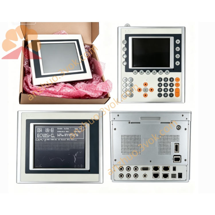
B&R 3IF787.9 Measurement Servo Module
Description
B&R 3IF787.9 Measurement Servo Module - Detailed Product Description
I. Basic Information
B&R 3IF787.9 is a aPCI bus measurement servo control module launched by Austria-based B&R, specifically designed for the 2005 series control systems and the Automation PC platform. It integrates POWERLINK real-time Ethernet and CAN fieldbus dual interfaces, combines high-precision measurement acquisition and servo motion control functions, and enables precise positioning of motion axes, speed closed-loop control, physical quantity measurement such as flow/position, and multi-device collaborative management. It is a core component for integrated measurement and servo control in industries such as packaging, textiles, and machine tools, and is suitable for installation in standard aPCI slots in control cabinets.
II. Core Technical Parameters
(1) Hardware Interface Configuration
POWERLINK Interface (IF2): Type 3 interface, compatible with POWERLINK V1/V2, supports master/slave station configuration, standard RJ45 connector, transmission rate 100 Mbps, single segment maximum distance 100 meters, used for real-time servo motion control and high-speed data interaction.
CAN Bus Interface (IF1): 4-pin male multi-point connector, supports CAN 2.0A/B and CANopen protocols, maximum baud rate 500 kbps, maximum communication distance 1000 meters when 125 kbps, used for measurement sensor data acquisition and auxiliary equipment control, wiring requires separate purchase of TB704 terminals.
System Bus: Standard aPCI bus, compatible with B&R 2005 series CPUs, Automation PC 910, etc., powered directly by the slot, no additional power supply required.
Electrical Isolation: POWERLINK, CAN interfaces are completely isolated from the system side 2500V AC, suppressing common-mode interference, surge voltage, ensuring measurement accuracy and servo control stability.
(2) Electrical Performance Indicators
Power Supply: 3.3V DC ±10%, 5V DC ±10%, powered through the aPCI slot.
Power Consumption: Typical 2.5W on 3.3V side, typical 0.5W on 5V side, total typical power consumption 3.0W; 750mA current on 3.3V side, 100mA current on 5V side, low power consumption suitable for compact cabinet power supply.
Anti-interference: Compliant with IEC 61000-6-2/4 standards, resisting strong electromagnetic interference from frequency converters, motors, etc., ensuring measurement and control accuracy.
(3) Environmental Adaptability Parameters
Operating Temperature: 0°C to + 60°C (horizontal standard installation), vertical/high-load scenarios require reduced usage.
Wide Temperature Storage: -25°C to + 70°C, suitable for long-term storage and transportation.
Humidity: 5% to 95%, no condensation, avoiding humidity-induced drift or short circuits in accuracy.
Protection Grade: IP20, dust-proof and solid foreign object-proof, suitable for clean and dry environments in control cabinets.
Vibration/Impact: Compliant with IEC 60068-2-6 (vibration), IEC 60068-2-27 (impact) standards, able to withstand industrial site mechanical vibration.
(4) Measurement and Servo Control Performance
Servo Control Performance: POWERLINK master station can support up to 32 servo slave stations, the shortest bus cycle is 100 μs, supports position/velocity/torque closed-loop control, positioning accuracy can reach ±1 pulse, suitable for high-precision synchronous motion scenarios. Measurement acquisition performance: Through the CAN bus, connect flow, pressure, position, temperature and other measurement sensors. Support pulse / analog signal acquisition. Measurement accuracy ±0.1% FS. Sampling frequency up to 1kHz. Support cumulative quantity calculation and data storage.
Protocol support: Fully support POWERLINK (V1/V2), CAN 2.0A/B, CANopen. Compatible with TCP/IP. Native support for dual-bus protocol conversion and measurement - servo data linkage.
System compatibility: Compatible with the Automation Studio development environment. Supports servo parameter configuration, measurement calibration, remote diagnosis and firmware online upgrade. Seamless compatibility with the 2005 system and the Automation PC ecosystem.
III. Core measurement and servo control functions
(1) High-precision servo motion control
Can be configured as a POWERLINK master station to manage slave stations such as servo drives and encoders, achieving precise position closed-loop positioning, stable speed closed-loop operation, and torque closed-loop tension control; supports multi-axis synchronization, electronic gears, electronic cams, etc. Motion modes. The shortest bus cycle is 100μs, ensuring high-speed dynamic response and micrometer-level control accuracy, suitable for high-precision motion scenarios such as robots, CNC machines, and packaging machinery.
(2) Multi-channel measurement data acquisition and processing
Connect various measurement sensors through the CAN bus. Support flow accumulation, length measurement, position detection, pressure / temperature monitoring, etc. Built-in high-precision measurement algorithms can filter, calibrate, and compensate sensor signals to eliminate temperature drift and interference errors. Measurement accuracy reaches ±0.1% FS. Support real-time measurement data display, historical data storage, over-limit alarm, and cumulative quantity reset to meet the precise measurement requirements of industrial processes.
(3) Measurement - servo linkage control
Core implementation of closed-loop linkage between measurement data and servo motion. Can automatically adjust servo speed, position or start/stop actions according to the measurement value. For example, in the packaging industry, when the set weight / length is reached, the servo automatically stops or switches to a different workstation; in the textile industry, adjust the servo torque in real time based on the tension measurement value to ensure constant fabric tension and achieve "measurement detection - motion adjustment" integrated control, improving production accuracy and efficiency.
(4) Dual-bus data bridging and protocol conversion
Support bidirectional data communication between the POWERLINK servo control network and the CAN measurement bus. Can forward servo operation status (position, speed, fault) to the CAN bus, or feedback CAN measurement data, sensor status to the POWERLINK control system. Native protocol conversion function simplifies heterogeneous network architecture, enabling seamless connection between servo systems and measurement equipment, reducing system integration costs.
(5) Bus status monitoring and fault diagnosis
Equipped with multiple LED indicators, real-time display of module power supply, POWERLINK connection / transmission / fault, CAN communication / fault, measurement / servo alarm status. Combined with the Automation Studio software, can remotely monitor servo axis position / speed / load, measurement real-time value / cumulative value, bus communication load rate. Support fault location, log recording and abnormal warning, quickly identify servo overload, measurement drift, bus interruption and other issues, reducing maintenance difficulty.
(6) Hot-swappable and flexible system expansion
Compatible with the 2005 system hot-swappable function. Can plug and replace modules without stopping the controller. No downtime maintenance required. Through the aPCI slot, multiple modules can be installed in parallel, flexibly expanding the number of servo control axes and measurement channels, and constructing a large-scale, hierarchical measurement-servo control system, which is suitable for the expansion requirements of different-sized automated production lines.
IV. Product Features
Integrated Measurement-Servo Integration: Integrating high-precision measurement acquisition and POWERLINK servo control functions in one module, this module takes care of both process measurement and motion control, simplifying hardware configuration and reducing equipment costs.
Industrial-grade High Reliability and High Precision: Using industrial-grade components and a fanless design, with a wide temperature operating range and strong anti-interference capability; servo positioning accuracy ±1 pulse, measurement accuracy ±0.1% FS, ensuring long-term stable operation in harsh environments.
Hard Real-time Linkage and Open Compatibility: POWERLINK microsecond-level bus cycle, supporting measurement-servo real-time closed-loop linkage; compatible with CANopen for old measurement equipment, suitable for upgrading scenarios of new and old systems.
Compact Modular Design: Standard aPCI size, small in volume, can be directly installed in the control cabinet slot, occupying little space, suitable for limited cabinet layouts, and installation is convenient and efficient.
Intelligent Diagnosis and Easy Maintenance: Dual guarantee of LED status indication + remote diagnosis software, quickly locating measurement/servo faults; supports hot swapping and online firmware upgrade, maintenance does not require downtime, reducing operation and maintenance costs.
Beckhoff Ecosystem Seamless Compatibility: Fully compatible with 2005 system, Automation PC, and Automation Studio environment, unified configuration, programming, and maintenance, strong compatibility, good scalability.
Global Certification Compliance: Certified by CE, UKCA, KC, cULus HazLoc, etc., compliant with industrial safety and electromagnetic compatibility standards, suitable for use in global industrial sites.
V. Application Scenarios
Packaging Machinery Measurement-Servo Control: Used in food, pharmaceutical, and chemical product packaging, collecting weight/length measurement data via CAN bus, linking POWERLINK servo control for feeding, cutting, and sealing actions, achieving precise quantitative packaging, improving packaging accuracy and efficiency.
Textile Machinery Tension and Length Control: Connecting tension sensors and length encoders, real-time measuring tension and fabric length, servo closed-loop regulating winding/laying speed and torque, ensuring constant fabric tension and precise length, suitable for spinning, weaving, and dyeing equipment.
CNC Machine Tool Positioning and Feed Control: As the POWERLINK master station controlling servo axes, achieving high-precision positioning and feed motion; accessing tool position and cutting force sensors via CAN bus, real-time monitoring of processing status and adjusting servo parameters to improve processing accuracy and product qualification rate.
Logistics Sorting and Conveying Line Control: Collecting item weight and size measurement data via CAN bus, linking servo control for sorting mechanism actions, achieving automatic sorting and precise conveying; suitable for e-commerce logistics, warehouse sorting, etc., improving sorting efficiency and accuracy.
Industrial Process Flow/Pressure Control: Used in water treatment, chemical, and energy industries, collecting flow, pressure, temperature, etc. measurement data, linking servo control for valve opening degree and pump speed, achieving flow/pressure closed-loop regulation, ensuring process parameters stability.
VI. Installation and Usage Precautions
Installation Environment Requirements: Modules need to be installed in a sealed control cabinet, maintaining ventilation, dryness, cleanliness, and dust-free; the environmental temperature should be controlled within 0℃ to + 60℃, away from damp, corrosive gases, strong heat sources, and frequency converters, large-power motors, etc., strong electromagnetic interference sources, to avoid affecting measurement accuracy and servo control stability. Installation operation specifications: Before installation, the power supply of the controller and control cabinet must be cut off to prevent damage to the module due to live operation; Align the module with the aPCI slot and push it in smoothly to ensure that the gold fingers are fully in contact without any deviation or looseness; Tighten the fixing screws; CAN bus wiring requires the use of dedicated TB704 terminals, and the wiring should be firm without any looseness.
Wiring and wiring requirements: The POWERLINK port uses standard shielded twisted pair, the RJ45 interface should be firmly inserted, and the shield layer should be grounded at one end; CAN bus uses dedicated shielded cables, keep away from power/high-voltage cables, avoid long-distance parallel wiring, and reduce electromagnetic interference; The wiring of the metering sensor should use shielded cables, be separately laid, avoid being in the same trough as the power lines, and prevent signal interference leading to measurement errors.
Parameter configuration and debugging: After powering on, identify the module through Automation Studio, configure the POWERLINK master/slave mode, bus cycle, servo axis parameters (position loop/velocity loop gain, limit), configure CAN bus baud rate, node ID, metering sensor parameters (range, calibration coefficient, filtering method); Configure the metering-servo linkage logic (trigger conditions, adjustment parameters); Download parameters and restart the module to take effect; During debugging, check the LED status, monitor the servo operation and metering data, and troubleshoot issues such as accuracy drift and motion jitter.
Maintenance and care: Monthly check the fixation of the module, whether the wiring is loose, and whether the LED status is normal. Use a dry soft cloth to clean the surface dust. Avoid dust accumulation affecting heat dissipation and accuracy; Avoid frequently plugging and unplugging the module to prevent gold finger wear; Firmware upgrade requires operation through Automation Studio. During the upgrade process,严禁 power off or plug/unplug the module to prevent firmware damage.
Precautions for fault handling: When the measurement error exceeds the limit or the servo operation is abnormal, first check the sensor wiring, calibration parameters, servo gain settings, and bus load rate, and gradually troubleshoot; Do not plug or unplug the faulty module while powered on to prevent short circuits or electric shocks; When the fault cannot be resolved, contact B&R's official technical support. Do not attempt to disassemble and repair by yourself to avoid damaging the module or expanding the fault.
VII. Quality Assurance and After-sales
B&R 3IF787.9 is an original B&R product with a 12-month warranty period. During the warranty period, non-human damage and faults caused by improper use are eligible for free repair or replacement services; Global warranty is supported. You can query warranty information and apply for after-sales support through B&R's official website, customer service hotline, or authorized dealers. At the same time, provide technical consultation, selection guidance, remote debugging, on-site technical support, etc., to help users quickly complete module deployment, system debugging, and daily maintenance, ensuring the stable operation of the automation system.
Get a Quote