
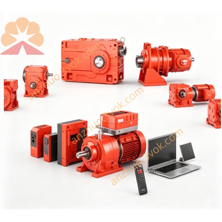
SEW ASI-Bin AS Interface Module
Description
1. Full Name & Meaning
ASI = AS‑Interface (Actuator‑Sensor Interface): a 2‑wire industrial bus for sensors/actuators.
Bin = Binary: refers to discrete ON/OFF signals (1/0).
ASI‑Bin = ASi binary I/O device/channel, typically with 4 digital inputs + 4 digital outputs (4DI/4DO).
2. ASi Bus Basics
Physical layer: Yellow flat 2‑wire cable, 30 V DC power + 167 kbps data over the same pair.
Topology: Bus/tree/star; max 100 m without repeaters (up to 600 m with repeaters).
Master‑slave: 1 master controls up to 62 slaves (ASi‑3: 31 slaves / 5 ms cycle; ASi‑5: 62 slaves / 10 ms cycle).
Data frame: Each slave has 4 input bits + 4 output bits (8 bits total) → “Bin” (binary) I/O.
3. Typical ASI-Bin Devices
Slave modules (most common)
IP20 (cabinet): e.g., Siemens 3RK1 200‑0AA02, 4DI/4DO, ASi‑3 standard.
IP65/67 (field‑mounted): e.g., Bihl+Wiedemann BWU2045, waterproof, installed near machines.
Signal assignment
Input Bin (4 bits): Sensor status (e.g., 1 = active, 0 = inactive).
Output Bin (4 bits): Actuator control (e.g., 1 = energized, 0 = de‑energized).
4. Key Specifications (General ASI-Bin)
Signal type: Binary (discrete), 24 V DC compatible.
I/O count: 4DI / 4DO per slave (standard).
Voltage: 30 V DC (bus‑powered).
Cycle time: 5 ms (ASi‑3) / 10 ms (ASi‑5).
Protection: IP20 (cabinet) or IP65/67 (field).
Lifetime: >10,000,000 cycles (ball bearing).
5. Applications
Conveyor systems
Packaging machinery
Automotive assembly lines
Process control (valves, solenoids, limit switches)
Get a Quote