
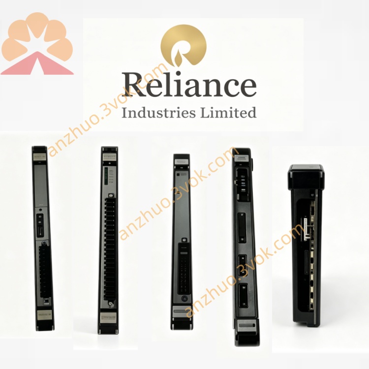
0-60031-1
Description
Model Number Definition
0-: Standard Reliance board prefix60031: Series identifier (Resolver & Driver I/O Module)1: Hardware revision (1st version, standard resolver interface)
Technical Specifications
Module Type: Resolver Interface + Isolated Driver I/O
Compatibility: AutoMax SA 3000 series AC/DC drives
Resolver Interface: 1-channel (sine/cosine, 2kHz excitation)
I/O Isolation: 2500Vrms (galvanic isolation)
Logic Voltage: +5V DC (backplane)
Resolver Supply: ±12V DC (on‑board)
Operating Temperature: 0–55°C
Storage Temperature: -20–70°C
Dimensions (W×H×D): ~30×220×180mm
Weight: ~1.6kg
Mounting: Standard slot in SA 3000 rack
Status LEDs: PWR, ACT, FLT
Interface & Communication
Front Panel:
Resolver Connector: 9‑pin D‑sub (excitation + sine/cosine feedback)
I/O Terminal Block: Isolated digital inputs/outputs (drive enable, fault, interlock)
LEDs:
PWR (green): On = +5V OK
ACT (yellow): Blinking = resolver signal activity
FLT (red): On = signal loss/overload
Backplane Edge Connector:
Power: +5V, ±12V, GND
Data: 16‑bit position/speed data to main control
Control: I/O status, fault reset
Core Functions
Resolver Signal Conditioning: Generates 2kHz excitation; amplifies/filters sine/cosine signals; converts to digital position/speed data.
Closed‑Loop Speed/Position Feedback: Provides high‑resolution feedback for precise motor control (vs. encoders in harsh environments).
Isolated Driver I/O: Interfaces drive control signals (enable, run, fault) with external systems; isolates high‑voltage power from low‑voltage logic.
Fault Detection: Monitors resolver signal loss, phase error, or overload; triggers FLT LED and drive shutdown.
Signal Buffering: Buffers digital data for noise immunity in industrial EMI environments.
Applications
AutoMax SA 3000 Drives: High‑power AC/DC drives for metal rolling, paper machines, extruders, cranes (where resolver feedback is preferred over encoders).
Harsh Environment Motion Control: High vibration, dust, or moisture conditions (resolvers more robust than encoders).
Legacy System Maintenance: Replacement for failed 0-60031-1 modules to restore closed‑loop control without full upgrade.
Precision Speed Regulation: Lines requiring tight speed/position accuracy (e.g., web processing, coil winding).
Usage & Maintenance
Installation
Power OFF only: Insert into designated SA 3000 rack slot; secure with front‑panel screws. No hot‑swap.
Wire resolver to 9‑pin D‑sub; connect I/O to terminal block per Reliance pinout.
Configuration
Set drive parameters for resolver feedback (excitation frequency, pole pairs) via keypad/software.
Calibrate resolver offset for accurate position tracking.
Routine Maintenance
Every 3–6 months: Power off; clean dust from connectors/PCB; check resolver cable for damage.
Verify LEDs: PWR ON, ACT blinking during normal operation.
Troubleshooting
No speed feedback: Check resolver wiring, excitation voltage, and D‑sub connections.
FLT LED ON: Inspect resolver cable for shorts; verify signal amplitude; check for EMI.
Intermittent errors: Clean D‑sub contacts; use shielded resolver cable; relocate away from high‑voltage cables.
Storage & Shipping
Store in anti‑static bag at -20–70°C, dry/dust‑free.
Ship with cushioning; avoid bending PCB or damaging D‑sub/terminal block.
Get a Quote