
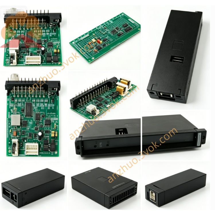
0-60017-1
Description
Model Interpretation
0-: Prefix for Reliance standard board
60017: Product series number (for PMI system main control CPU board)
1: Hardware revision version number (first official version, replacing prototype version 0-60017-A) Technical Specifications
Processor: 16-bit dedicated industrial CPU, with a main frequency of 8 MHz
Memory: RAM 16KB (power-on data retention), ROM 64KB (firmware program)
Power supply: +5V DC/3A, ±15V DC/0.5A (power supply from the back panel)
Control cycle: Current loop 1ms, speed loop 10ms
Feedback interface: Compatible with encoder (5V differential), Resolver (10Vrms/400Hz)
Operating temperature: 0–55°C; Storage: -20–70°C
Size (width × height × depth): Approximately 30×220×180mm
Weight: Approximately 1.8kg
Installation: Special slot in the center of the PMI rack, fixed on the front panel
Insulation withstand voltage: Logic and I/O 1kV AC/1min
Interface and communication configuration
Front panel:
LED digital tube: 2 digits, displaying fault codes / operating status
LED indicator lights: RUN (operation), FLT (fault), COM (communication)
Buttons: 3 keys (mode / confirm / reset), local parameter setting
Back panel pins:
Power bus: +5V, ±15V, GND
Data bus: High-speed communication with I/O board, power board, driver board
Control signals: System enable, emergency stop, interlock
Communication: Supports PMI internal bus, optional RS-232 serial port (requires expansion board) Core function
Closed-loop control operation: Execute speed loop and current loop PID regulation, and output precise PWM control signal to the driver board.
System logic management: Handle start/stop, forward/reverse, emergency stop, interlock and other timing logic.
Parameter storage and retrieval: Store motor parameters, PID parameters, limit values, etc., and retain them even during power loss.
Fault diagnosis and protection: Overcurrent, overvoltage, overload, overheating, abnormal feedback detection, trigger protection and display fault codes.
I/O signal interaction: Exchange digital/analog signals with the I/O board in real time, adapt to on-site sensors and actuators. Applicable scenarios
Industrial direct current drive: Large power DC motors for equipment such as rolling mills, paper machines, extruders, cranes, conveyors, etc. are driven by this system.
Core control of PMI system: Compatible with all PMI racks (such as the 57C series), directly replacing the old version 0-60017-A.
High-precision speed regulation scenarios: Required for rapid response and stable speed accuracy ≤ ±0.01% for tension control and synchronous transmission equipment.
Maintenance of outdated production lines: Replacement of main control spare parts for out-of-service equipment to avoid entire line renovation and reduce costs.
User and maintenance instructions Installation
When the power is off, insert the PMI rack into the central slot and tighten the screws on the front panel; do not perform hot swapping to prevent the gold fingers from being burned.
The installation location should be far away from power lines and heat-generating components to ensure a smooth air circulation path for heat dissipation. Parameter settings
The rated parameters, PID gains, limit values, etc. of the motor can be set through the front panel buttons or the upper computer software.
After modifying the parameters, they need to be saved so that they will not be lost even after power off; to restore the factory settings, press the reset button for 5 seconds continuously.
Daily maintenance
Every 3-6 months, power off and blow away the dust, check if the gold fingers are oxidized and if the terminals are loose.
Observe the LED status: RUN is always on normally; FLT flashes → fault; COM is not lit → communication interruption.
Fault troubleshooting
No running display: Check the back panel + 5V power supply, gold finger contact, board card fuse.
Unstable speed control: Check PID parameters, feedback signals, motor excitation, load fluctuation.
Frequent faults: Check cooling, power ripple, external interference, board card aging.
Get a Quote