
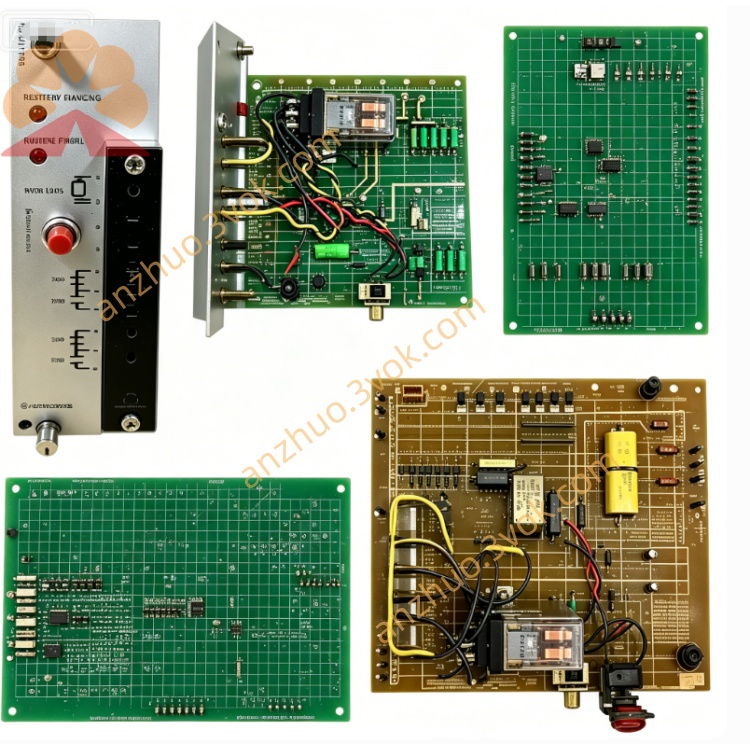
Reliance 0-60002-5
Description
Technical Specifications
Power Supply: 12V DC (Backplane Power Supply)
Power Consumption: ≤ 1W
Temperature Range: 0–50°C (Operation), -20–70°C (Storage)
I/O Channels: 8 Digital Inputs, 8 Digital Outputs
Processor: Dual FPGA + 25 Integrated Circuits
Dimensions (Width × Height × Depth): Approximately 30×220×180mm
Weight: Approximately 1.8kg
Installation: PMI Rack Right Slot, Front Panel Screws for Fixation
Interface and Communication Configuration
Front Panel Connectors:
Feedback: 18-pin, Encoder / Speed Sensor Feedback
Fwd Gates: 14-pin, Forward Drive Gate Signal
Rev Gates: 14-pin, Reverse Drive Gate Signal
Fdbk & Gates: Composite Signal Interface
Backplane Interface: Right-angle Gold Finger, Connecting PMI Backplane Communication and Power Supply
Communication: Built-in RS-485, Supports Data Interaction with Host Computer / PLC
Status Indication: Green OK Indicator Light (Normal Always On, Fault Off) Core function
Signal digitization: High-speed sampling and analog-to-digital conversion of armature / excitation current and voltage signals.
Closed-loop control: Achieve dual closed-loop regulation of armature voltage speed control and excitation weak magnetic speed control.
Drive signal generation: Output positive / reverse gate trigger signals to control the conduction timing of the power module.
Fault monitoring: Built-in watchdog (Watchdog), automatically shuts down the drive upon timeout, with overcurrent / overvoltage / overheat protection logic.
Redundancy support: Supports system redundancy configuration, with hot-swappable design to reduce downtime. Applicable scenarios
Industrial drive: Large power DC motors for drive of rolling mills, extruders, paper machines, conveyors, cranes, etc.
High precision control: Required for precise control of speed/torque and high dynamic response.
Upgrade of old systems: Replacement of the same series of old control cards (such as 0-60002-3/4), compatible with the original frame and wiring.
User and maintenance instructions Installation
This is only applicable to the right slot of the PMI rack. After insertion, tighten the two fixing screws on the front panel.
Installation / disassembly under power-off condition. Avoid thermal insertion to prevent interface damage.
Connections
Connect the feedback (encoder / tachometer), drive gate signal according to the markings. Verify the pin definitions to prevent short circuits.
The communication line uses shielded twisted pair, keeping away from power lines to reduce interference.
Daily maintenance
Regularly (3–6 months) power off and blow dust off the board, check if the connectors are loose or oxidized.
Observe the status of the OK indicator light: always on indicates normal, flashing / extinguished requires troubleshooting of power supply, backplane communication or hardware faults.
Troubleshooting
The indicator light is not on: Check the 12V power supply on the backplane and the contact of the gold fingers.
Abnormal drive: Verify the feedback wiring, output of the gate signal, and check the status of the FPGA and the driver chip.
Get a Quote