
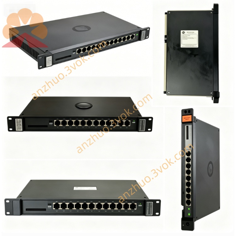
0-57C408-B
Description
Model Definition
0-57C408-B: Full part number
Leading 0: Factory-original, unmodified unit
57C408: Base model (Power Module Interface)
B: Revision B (hardware/ firmware update, enhanced protection)
Series: AutoMax 57C Series (Reliance PLC/DCS) / DCS 5000 Series
Variant: Standard industrial revision B (no conformal coating/extended temp)
Technical Specifications
General
Brand: RELIANCE (Reliance Electric / Baldor Reliance / ABB)
Type: Power Module Interface (PMI) / Analog I/O & Drive Controller Module
Form Factor: 1-slot AutoMax rack-mount (slots 0–4 compatible)
Dimensions: 11.75 in (H) × 3.5 in (W) × 1.2 in (D) approx
Weight: ~0.38 kg (0.84 lbs)
Operating Temperature: 0°C to +60°C (standard)
Storage Temperature: -40°C to +85°C
Humidity: 5%–95% non-condensing
Isolation: 1500 Vrms (rack-to-drive/analog circuits)
Certifications: CE, RoHS, UL listed
Manual: D-2717 (official instruction manual)
Electrical
Backplane Power: +5 VDC ±5% (from AutoMax rack PSU)
Current Draw: 0.8 A (typical), 1.2 A (max)
Input Voltage (Drive Side): 220 VAC (50 kHz frequency range)
Protection: Overvoltage, overcurrent, ESD, transient suppression (revision B enhanced)
Interface & Signal
Power Module Interface: Connects to 57C494 (23A power supply)
Analog I/O Interface: 16-bit resolution, ±15 VDC signal range
Drive Controller Interface: Compatible with SD3000/SF3000/SA3000 series drives
Backplane: AutoMax Multibus (2 Mbps)
Signal Channels: 8 analog input channels, 4 analog output channels (isolated)
Interface & Communication Configuration
Physical Interfaces
Front Panel:
Green OK LED (steady = run, flash = fault)
Red FAULT LED (fault code trigger)
7-segment LED display (fault code readout)
Backplane: AutoMax proprietary edge connector (power + Multibus + I/O signals)
Drive/Power Side: Terminal strip for 220 VAC, analog signals, and drive control wiring
LED Indicators
OK: Green (steady = normal; flashing = self-test/fault)
FAULT: Red (on = critical fault; off = normal)
7-segment Display: Fault codes (e.g., E1 = overvoltage, E2 = overcurrent)
Core Functions
Power Module Interface: Bridges AutoMax rack and 57C494 power supply, distributing stable DC power to system modules.
Analog I/O Processing: Converts analog signals (±15 VDC) between field devices (sensors, potentiometers) and the AutoMax CPU.
Drive Controller Communication: Transmits control signals to/from SD3000/SF3000/SA3000 drives for motion control.
Signal Isolation: 1500 Vrms isolation protects rack circuits from drive-side noise/voltage spikes.
Fault Monitoring: Real-time detection of overvoltage, overcurrent, and signal errors; displays codes via 7-segment LED.
System Compatibility: Works with all AutoMax 57C series processors and DCS 5000 racks; mixable with legacy modules.
Application Scenarios
Legacy AutoMax/DCS 5000 Retrofits: Direct replacement for 57C408-B in aging industrial control systems.
Motion Control Systems: Conveyors, cranes, machine tools, and material handling equipment with Reliance drives.
Process Control: Analog signal monitoring/control for water treatment, packaging, and manufacturing lines.
Drive Integration: Connecting AutoMax PLCs to SD3000/SF3000/SA3000 series DC drives.
General Industrial Automation: Factory floors requiring reliable analog I/O and drive control interfacing.
Usage & Maintenance Instructions
Installation
Power Off: De-energize the AutoMax rack and connected drives before insertion.
Insert Module: Align with slots 0–4; push firmly until backplane connector seats.
Secure: Tighten captive screws (torque 0.8–1.0 N·m).
Wiring: Connect 220 VAC, analog signals, and drive control wires to the terminal strip; use shielded cable for noise immunity.
Operation
Power-On: OK LED flashes (~3–5 s) during self-test; 7-segment LEDs show init codes.
Normal: OK steady green; FAULT off; no fault codes displayed.
Fault: FAULT red on; OK flashes; 7-segment shows code → check wiring, drive power, or analog signals.
Get a Quote